2
MODEL 8870 THERMOSTAT
The Model 8870 Thermostat is field configurable to operate
single and multi-stage separate heating and cooling
equipment (such as furnace and air conditioner or roof top
units), or single and multi-stage heat pump systems. A menu
driven set up, using the message center display of the
thermostat, can be used to configure many other features.
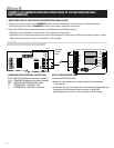
Network communication is non-isolated, full duplex RS-485
(RS-422). The ‘A’ terminals are the transmit pair while the ‘B’
terminals are the receive pair. This nomenclature uses the
computer or host as the reference, so transmit refers to the
lines on which the host transmits data to the thermostat
while receive refers to the lines on which the host receives
data from the thermostat. The baud rate is selectable
between 9600 and 19200. Up to 64 uniquely addressed
thermostats may reside on the same thermostat network.
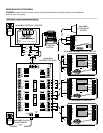
MODEL 8818 DISTRIBUTION PANEL
The Distribution Panel is a switch controlled communication
bus that can be wired to eight (8) Aprilaire Model 8870
thermostats. This allows thermostat communication
(transmit, receive or both) to be turned on and off at one
convenient location which simplifies installation and trouble
shooting. Each thermostat station on the distribution panel
has an on/off switch for power. This allows isolation of any
one thermostat to simplify troubleshooting. Order one
Distribution Panel per eight thermostats.
MODEL 8061 AND MODEL 8062 SUPPORT MODULES
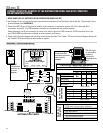
Support modules are used to either monitor or control
temperature or humidity at a location other than the
thermostat. They communicate with the thermostat using a
RS-485 protocol. Up to four support modules may be wired to
a thermostat, with each module able to support two sensors.
The Model 8061 has one onboard temperature sensor and
room for one offboard temperature sensor (sensor #1 &
sensor #2) while the Model 8062 has one onboard
temperature sensor (sensor #1) and one onboard humidity
sensor (sensor #2). All sensors can be configured as either a
control sensor (replaces thermostat temperature sensor as
control variable) or a monitor sensor (read only). An offboard
sensor such as a Model 8051 Flush Mount Sensor can
replace sensor #1 on the Model 8062 or both on the Model
8061. Each support module is addressed and each sensor
value can be accessed through thermostat commands. See
sensor literature for additional information.
FOR EASE OF INSTALLATION AND TROUBLE SHOOTING
DO THE FOLLOWING:
✔ Use Category-5 cable for all communication wiring.
✔ Check and recheck to ensure connection to the proper
terminals before powering up the thermostats. Use wire
color as a guide and be consistent.
✔ Use a Distribution Panel on all systems with more than
one zone. The trouble shooting benefits will outweigh the
cost of the Distribution Panel.
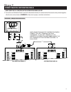
• If the thermostats are wired to a zone control panel, there is generally one set of input terminals supplying power to the
thermostats and dampers. This must be disconnected.
• If the thermostats are wired directly to HVAC equipment, the power must be shut off at the equipment. This can generally be
accomplished by turning off the disconnect switch located near the equipment. If an obvious disconnect switch is
unavailable, you will need to turn the circuit off using the fuse or circuit breaker. Remove the fuse or shut down the circuit
breaker serving the equipment.
DISCONNECT POWER TO ALL HVAC EQUIPMENT AND/OR ZONE CONTROL PANELS
Step 2
CAUTION
Failure to disconnect power could result in damage to the HVAC equipment or thermostats. Leave power disconnected
until all other electrical connections have been made and checked for accuracy.


