


ON
OFF
ON
OFF
ON
OFF
ON
OFF
ON
OFF
ON
OFF
ON
OFF
ON
OFF
OR
BL
BK
RD
2/
YB
B4 B8
24V
24Vc
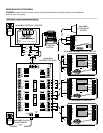
Communication Card
POWER
24V AC
485 SERIAL IN
OR BL BK RD
Y2
W1
24V(c)
24V
R
G
Y1
W2
CLK1
RS1
1
RS+v
RS2
CLK2
2
Model 8027
PLUG-IN TRANSFORMER
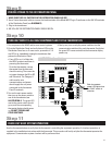
8800-8808 MODEL COMMUNICATION PANELS
RC
RH
G
W2
C
RSC
RSA
RSB
RSR
R
REF
Y2
B-
B+
A+
A-
BLU/WHT
ORG/WHT
BLU
GRN
ORG
BRN
MODEL 8870 THERMOSTAT
2-WIRE TSTAT
CABLE
CAT-5
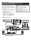
CAUTION!
TURN ALL DISTRIBUTION PANEL SWITCHES
OFF BEFORE DOING ANY WIRING.
IMPORTANT!
YOU MUST USE A SEPARATE POWER
SUPPLY FOR 8870 THERMOSTAT(S).
IMPORTANT!
YOU MUST ADDRESS 8840 SERIES
THERMOSTATS HIGHER THAN ANY MODEL
8870 THERMOSTAT ON THE NETWORK.
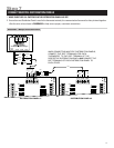
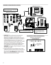
8840 SERIES THERMOSTAT
BLU/
WHT
ORG/
WHT
BLU
GRN
ORG
BRN
DEH Y1
HUM W1
R.V.-Cool (O)
.-Cool (O)
R.V.-Cool (O)
R.V.-Heat (B)R.V.-Heat (B)
Model 8027
PLUG-IN
TRANSFORMER
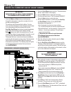
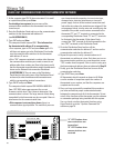
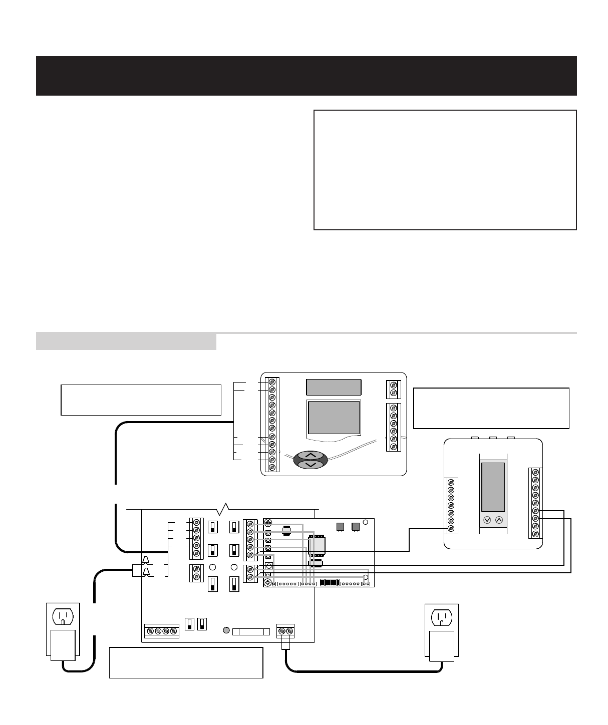
If adding a Model 8870 thermostat to a system using 8840
series thermostats (8844, 8846, 8847 or 8848), you must
change the power supply installation, modify the addressing
method and remove terminating resistors from the Model
8811 protocol adapter.
1. A separate power supply is required for Model 8870
thermostats and 8840 series thermostats. This requires
different wiring.
• If using a Model 8800-8808 Communication Panel, see
DIAGRAM 7 for wiring schematic.
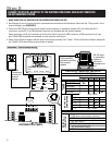
• If using a Model 8818 Distribution Panel you must use
the 8840 series thermostat with an 8809 Sub-base to
allow RS-485 communications to be connected directly
to the Distribution Panel. See DIAGRAM 8 for wiring
schematic.
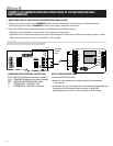
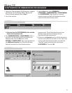
NOTE:
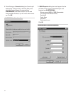
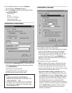
1. IF USING AN EXISTING HYPERTERMINAL
CONNECTION YOU MAY NEED TO UNCHECK THE
“SEND LINE FEEDS…” BOX.
2. THE MODEL 8870 HAS AN EXPANDED COMMAND
SET. REFER TO DP 10004345 FOR THE MODEL 8840
SERIES COMMAND SET.
SPECIAL CONSIDERATIONS FOR INSTALLING THE MODEL 8870 WITH THE
8840 SERIES COMMUNICATING THERMOSTAT
Appendix 1
DIAGRAM 7 – Adding an 8870 Thermostat
17