


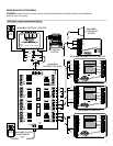
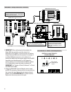

B+ B- REFA-
RCA+ A- B+ B-
A
B
A+
OFF ON
OFF ON
ON OFF
ON OFF
PWR
PWR
A
B
A
B
RCA+A-B+B-
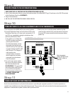
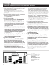
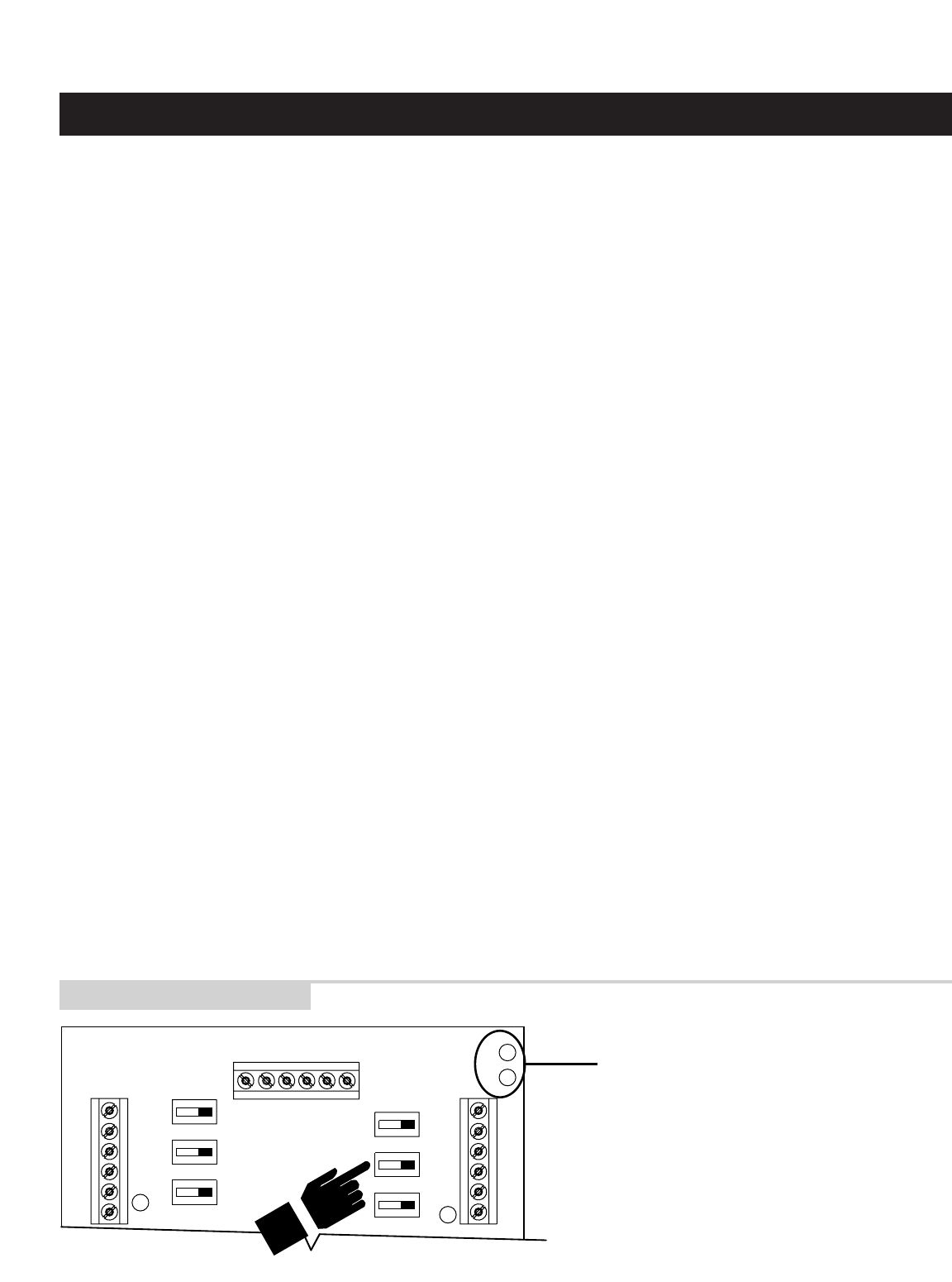
“A” LED flashes when
communications are
transmitted
“B” LED flashes when
communications are
received
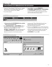
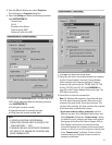
1. At the computer type SN? (it does not matter if it is small
or capital letters) then press Enter.
You should get no response because none of the
communication switches to the thermostats have been
turned on yet.
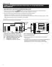
2. Go to the Distribution Panel and turn on the communication
switches for the thermostat with address #1
(see ILLUSTRATION 12).
3. Type SN? and press Enter.
The computer should respond SN1. This indicates that
the thermostat with address #1 is communicating.
• If no response, type in SN? and press Enter again. If it
still does not appear, go to the Distribution Panel make
sure the communication switches for the thermostat
with address #1 are on.
• If the “SN” response contained a number other than one,
the communication switches you turned on were for an
address other than number one. Now is the time to verify
that the thermostat names/locations match the addresses
shown on the Network Interconnection Worksheet
(ILLUSTRATION 3). There is room on the Distribution
Panel label (on the inside cover of the Distribution Panel
enclosure) to write the address and thermostat name
with the corresponding terminal connections.
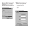
4. Type SN ID? and press Enter.
The computer should respond SN1 MODEL# 8870 REV:
Vx.x - RPC 2002; where x.x represent the current
firmware revision level. This is done to determine if the
communication is robust. The large amount of data being
transmitted by the thermostat may be corrupted if there is
interference on the communication lines.
• If the response is not exactly as shown, there is a
communication signal problem. The most likely sources
are a loose terminal connection, incorrect wire type,
damaged wire, electrical interference or incorrect
power supply. Look at all the terminal connections and
look at the wire where the insulation was stripped. If the
wire appears kinked, trim the wire and carefully strip the
insulation. Also, make sure the wires connected to the
thermostat “R” and “C” terminals is connected to the
corresponding Distribution Panel “R” and “C” terminals
for that particular thermostat. If this doesn’t help,
connect the “REF” terminal of all the thermostats to the
two “REF” terminals on the Distribution Panel.
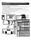
5. Go to the Distribution Panel and turn off the
communication switches for address #1 and turn on the
communication switches for address #2.
6. Repeat this process to verify communications to all
thermostats one address at a time. Each time you turn on
the communication switches to a new thermostat, a new
“SN” number should respond. If this is not the case, go to
the thermostats and address them as indicated in Step 12.
7. Finally, go to the Distribution Panel and turn on all the
communication switches.
8. Type SN ID? then press Enter.
All thermostats should respond as shown in #4. Make
sure the number of responses equals the number of
thermostats in your system, and that the responses are
complete and accurate.
9. Once you have successfully completed this procedure
you have verified that proper communication exists
between the computer and all of the thermostats. To test
out all of the functions of the thermostat, use the software
or automation package being installed with this system.
You can check out other thermostat functions using
HyperTerminal: go to the “Aprilaire Command Set”
section on page 19.
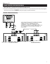
CHECK-OUT COMMUNICATIONS TO THE THERMOSTAT NETWORK
Step 14
ILLUSTRATION 12 – Com Switches
16