


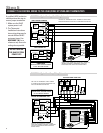
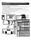
RC
RH
G
W2
C
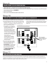
RSC
RSA
RSB
RSR
R
REF
Y2
B-
B+
A+
A-
BLU/WHT
ORG/WHT
BLU
GRN
ORG
BRN
BRN
GRN
BLU/WHT
ORG/WHT
BLU
ORG
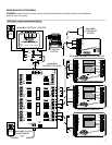
B+ B- REFA-
RCA+ A- B+ B- A+ A
-
A
B
A+
OFF ON
OFF ON
OFF ON
ON OFF
ON OFF
ON OFF
PWR
PWR
A
A
B
A
A
B
RCA+A-B+B-A+A-
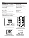
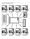
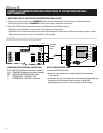
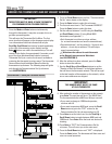
COMMUNICATION TERMINAL DEFINITIONS
B+/B- RECEIVE (reference automation system)
A+/A- TRANSMIT (reference automation system)
REF GROUND REFERENCE (see Note)
R THERMOSTAT VOLTAGE (hot)
C THERMOSTAT VOLTAGE (common)
GRN/WHT
GRN/WHT
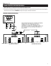
NOTE ON REFERENCE WIRE
Connect the REF terminals if:
• More than one transformer is used to power the thermostats
in the network
• Installation is in an environment that has excessive electromagnetic
interference from fluorescent lights, motors, or other EMI
generating devices, such as in an industrial or office setting
CAT-5
See NOTE
ON REF
WIRE
DEH Y1
HUM W1
R.V.-Cool (O)R.V.-Cool (O)
R.V.-Heat (B)R.V.-Heat (B)
8
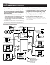
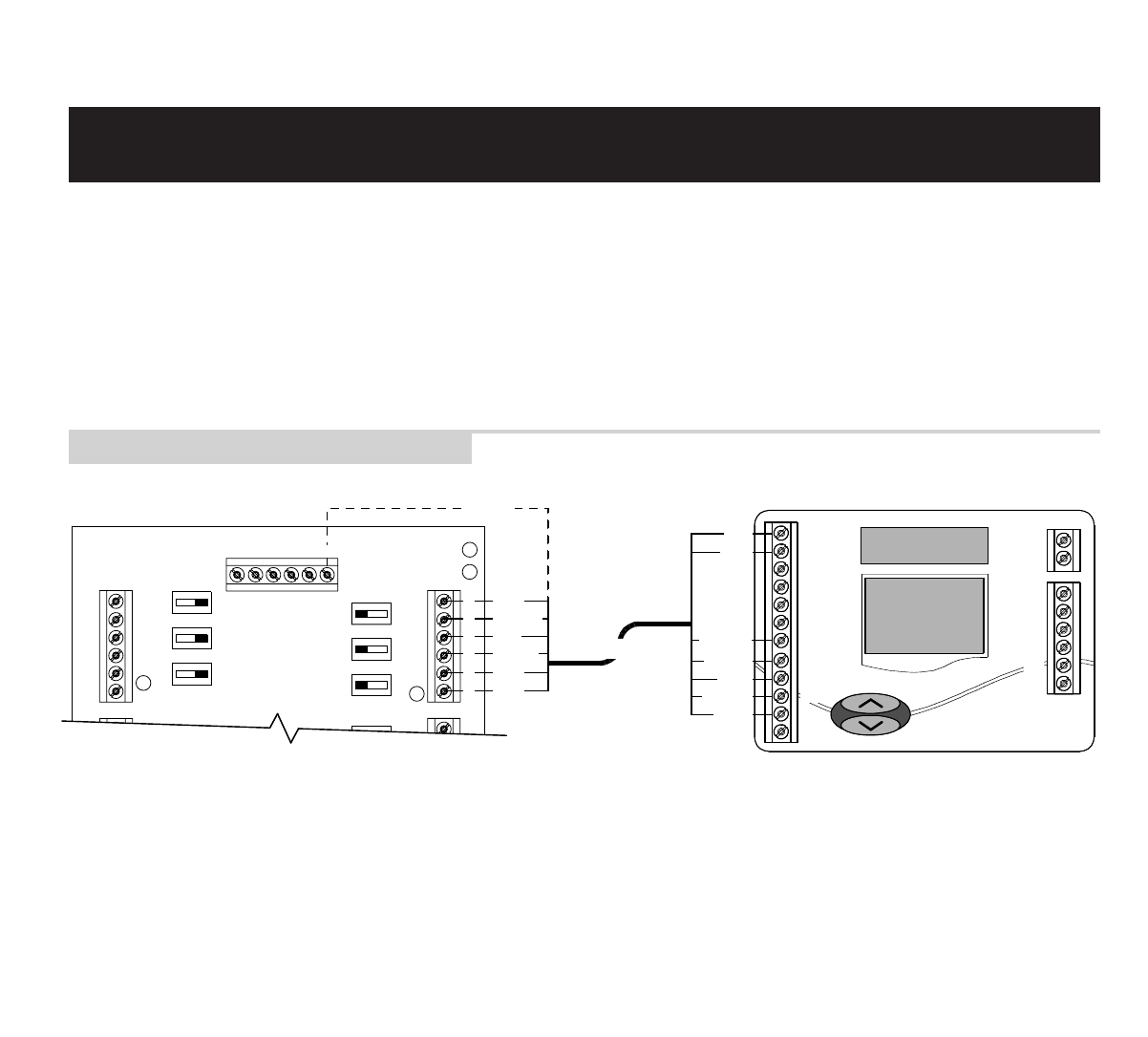
1. MAKE SURE THAT ALL SWITCHES IN THE DISTRIBUTION PANEL ARE OFF!
2. Connect the communication wires. DIAGRAM 4 shows how each thermostat is to be wired to the distribution panel.
• Use the wire colors shown in DIAGRAM 4 to help ensure proper, consistent connections.
3. Connect the REF terminal of each thermostat to the Distribution Panel REF terminals if:
• More than one transformer is used to power the thermostats in the network
• Installation is in an environment that has excessive electromagnetic interference from fluorescent lights, motors, or other
EMI generating devices, such as in an industrial or office setting
CONNECT THE COMMUNICATION AND POWER WIRES TO THE DISTRIBUTION PANEL
AND THERMOSTAT
Step 6
DIAGRAM 4 – Thermostat Communication Wiring