


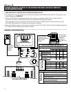


PROTOCOL ADAPTER WITH
COVER REMOVED
JP9
Place these 2
jumpers on just
one pin
RJ11 Connectors
Y2
W1
24V(c)
24V
R
G
Y1
W2
CLK1
RS1
1
RS+v
RS2
CLK2
2
Communication
Card
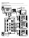
MODEL 8809 COMMUNICATING SUB-BASE
MODEL 8848 SHOWN
ORG/WHT
BLU
ORG
40VA
XFRMR
BRN
GRN
BLU/WHT
ORG/WHT
BLU
ORG
ORG
RED
BLK
BLU
40VA
XFRMR
2-WIRE TSTAT
CABLE
BLU/WHT
CAT-5
GRN
BRN
BLU/WHT
ORG
BLU
ORG/WHT
RED
BLK
YEL/BLU
RC
RH
G
W2
C
RSC
RSA
RSB
RSR
R
REF
Y2
B-
B+
A+
A-
BLU/WHT
ORG/WHT
BLU
GRN
ORG
BRN
MODEL 8870 THERMOSTAT
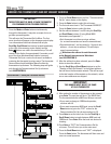
CAUTION!
TURN ALL DISTRIBUTION PANEL SWITCHES OFF
BEFORE DOING ANY WIRING.
CAT-5
IMPORTANT!
YOU MUST USE A SEPARATE POWER
SUPPLY FOR 8840 SERIES THERMOSTATS.
Model 8027 PLUG-IN TRANSFORMERS
BRN
GRN
IMPORTANT!
YOU MUST ADDRESS 8840 SERIES
THERMOSTATS HIGHER THAN ANY
MODEL 8870 THERMOSTAT ON THE
NETWORK.
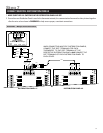
DEH Y1
HUM W1
R.V.-Cool (O)
.-Cool (O)
R.V.-Cool (O)
R.V.-Heat (B)R.V.-Heat (B)
RCA+ A- B+ B- R CA+ A- B+ B-
OFF ON
OFF ON
OFF ON
OFF ON
ON OFF
ON OFF
ON OFF
ON OFF
PWR
PWR
PWR
PWR
A
B
A
B
A
B
A
B
MAIN
PWR
ON OFF
RC
24VAC
FUSE
RCA+A-B+B-RCA+A-B+B-
MODEL 8818 DISTRIBUTION PANEL
2-WIRE TSTAT
CABLE
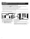
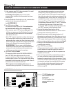
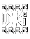
2. IMPORTANT! When addressing the thermostats, the
Model 8870 thermostat(s) must either be the first
addresses on the network, or there must be one address
skipped between 8840 series thermostats. For example, if
one Model 8870 thermostat were to be added to an
existing four 8840 series thermostat network then the 8870
thermostat must be addressed #1 or #6. Change the
existing address #1 to be #5 and add the 8870 as address
#1, or simply add the new thermostat as address #6.
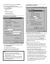
IMPORTANT: Set “Number of Stats On Network” to 32 and
Set BAUD Rate to 9600.
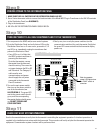
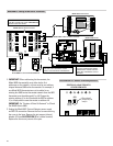
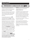
3. Unplug the Model 8811 Protocol Adapter power supply
and RS-232 connection. Remove the four screws securing
the cover to the base. Remove the pin jumpers (shunts)
labeled JP9 (see ILLUSTRATION 13 for relative location).
Replace the shunts on just one of the pins.
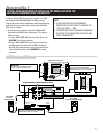
DIAGRAM 8
– Adding an 8840 Series Thermostat
ILLUSTRATION 13 – Remove Terminating Resistors
18