


9
13. Place casing gasket (351) against shoulder in casing.
14. Slide the pullout assembly into the casing (100). Drain slot
in stuffing box cover (184) should line up with drain connection
in casing. Install frame–to–casing bolts (370) and tighten evenly
while rotating shaft (122) by hand. If impeller ceases to turn
freely, stop tightening operation and adjust the impeller setting
with the adjusting bolts (370C and 370D) before resuming
tightening of frame-to-casing bolts (370).
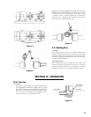
15. Impeller Clearance
The impeller clearance is an important factor in maintaining
optimum pump performance. The nominal clearance is .015”
with the recommended minimum being .008”. The actual
clearance setting is dependent on the specific operating
conditions, taking into account temperature, solids, etc. For
maximum service flexibility pumps are shipped from the factory
with the clearance set at .015”. The desired clearance is
obtained in the following manner:
a. Loosen bolts (370C and 370D).
b. Tighten bolts (370C) with turning shaft clockwise until
impeller starts to rub against casing.
c. Loosen bolts (370C) until a feeler gauge, corresponding
to the desired clearance, can be placed between the bolt
head and bearing housing.
d. Tighten bolts (370D) evenly. Bearing housing shaft and
impeller will be jacked to proper clearance from casing.
Tighten bolts (370C) and jam nuts on bolts (370D).
e. If desired, a dial indicator can be used instead of a feeler
gauge to check that the bearing housing has been moved
the correct distance.
V-D. Additional Details
An alternate method for setting inside mechanical seals is the
“Modified Visegrip Method”.
1. Follow assembly up to Step 7.
2. Assemble the gland with stationary seat and gaskets.
3. Install the shaft sleeve, if used on the shaft, and engage
groove in sleeve with drive pin (469) on shaft.
4. Slide gland assembly over the shaft or shaft sleeve.
5. Install the stuffing box cover and impeller. Establish a
preliminary rotor adjustment (refer to Section V–C–9).
6. Slide gland assembly against stuffing box. Do not bolt the
gland to the stuffing box.
7. Clamp the modified visegrip on the shaft or sleeve directly
behind and against the gland.
8. Leave the visegrip in place and remove the impeller and
stuffing box cover.
9. Lubricate the rotary portion of seal and slide it on the shaft
until it comes in contact with the stationary seat in the gland.
10. Compress rotary portion of seal to correct dimension as
shown on seal manufacturer’s drawing. Tighten set screws.
11. Remove visegrip and reinstall stuffing box cover and
tighten.
12. Reinstall impeller with O–ring.
13. Slide the gland assembly against the stuffing box and tighten
nuts evenly.
14. Refer to Step 12, etc.
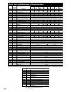
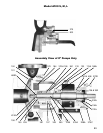
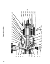
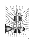
SECTION VI—PRODUCT DESCRIPTION
See pages 10, 11,12, 13 and 14 for Sectional
Views, Parts List and Materials of Construction.