


7
SECTION V—DISASSEMBLY AND REASSEMBLY
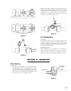
V-A. Disassembly
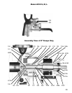
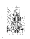
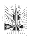
(refer to Sectional Views in Part VI)
1. Prepare pump for disassembly as follows:
a. Lock out power supply to motor.
b. Shut off valves controlling flow to and from pump.
c. Flush pump of all corrosive or toxic liquid, if required.
d. Remove all auxiliary tubing and piping.
e. Disconnect coupling and remove coupling spacer.
f. Drain oil.
g. On units with packed stuffing box, unbolt packing gland
(107).
2. Disassemble pump as follows:
a. Place sling from hoist through eyebolt (132). On S units,
place sling through frame (228A) above shaft (122).
b. Remove frame foot hold down bolts.
c. Remove bolts (370) holding frame (228A) or frame adapter
(108) to casing (100).
d. Slide back pull–out assembly from casing, using jacking
bolts (418) provided.
e. Remove casing gasket (351).
f. Unscrew impeller (101) from shaft (122). The threads are
right hand. Remove O–ring (412A) which seals between
the impeller and shaft or sleeve.
g. (1) On units with inside mechanical seal, remove gland
stud nuts (355) and carefully slide gland toward bearing
frame (228A).
(2) On units with outside mechanical seal, loosen set
screws holding rotary portion of seal to shaft and slide
seal toward bearing frame. Remove gland stud nuts and
carefully slide gland off studs.
h. Remove stud nuts (370H) which hold stuffing box cover
(184) to frame adapter. Pull stuffing box cover from frame
or adapter. Slide sleeve (if any) off shaft.
i. On units with mechanical seal, loosen set screws holding
rotary portion of seal to shaft, and carefully slide seal and
gland assembly off shaft. On units having a shaft sleeve,
it is not necessary to remove rotary portion of seal from
sleeve unless replacement of seal is required.
j. Slide deflector (123) off shaft.
k. Scribe shaft at coupling hub for proper positioning of hub
during reassembly and remove hub.
l. Remove bearing housing bolts (370C). Using impeller
adjustment bolts (370D) for jacking, remove shaft and
bearing assembly from frame. This will include the shaft,
both bearings (112A) and (168A), and bearing housing
(134A). Do not lose or damage O–ring (496).
m. Remove inboard bearing (168A) using a bearing puller.
Never use a hammer to drive shaft through bearing!
Protect bearing from contamination.
n. Scribe bearing housing for proper positioning prior to
disassembly on S, M and L models, remove bearing housing
retaining ring (361A) and slide bearing housing off ball
bearing. Do not damage oil seal (332A). On X units,
remove bearing end cover bolts (109A) and slide cover
off shaft. Do not damage oil seal (332A). Slide bearing
housing off shaft.
o. Straighten tang in lock washer and remove bearing
locknut (136) and lock washer (382). Remove ball bearing
(112A) using a bearing puller. Protect bearing from
contamination.
p. On units with stuffing boxes, remove lantern ring (105)
and packing rings (106) from stuffing box cover (184).
V-B. Inspection and Parts
Replacement Guidelines
1. Impeller—Replace if impeller shows excessive erosion,
corrosion, extreme wear, or vane breakage. O–ring groove and
impeller hub must be in good condition. Check impeller balance
if possible. Reduction in hydraulic performance and reduced
mechanical seal, packing or thrust bearing life may be caused
by excessive impeller wear.
2. Shaft—Check for runout (.005” max) to see that shaft has
not been bent. On pumps without shaft sleeves, shaft surface in
stuffing box area must be smooth and free of grooves. Bearing
seats and oil seal area must be smooth and free of scratches or
grooves. Shaft threads must be in good condition. Metalize or
replace shaft if necessary.
3. Shaft Sleeve—Sleeve surface in stuffing box must be smooth.
If grooved, replace or metalize.
4. Mechanical Seal—Seal faces, gaskets, and shaft sealing
members must be in perfect condition or leakage may result.
Replace worn or damaged parts.
5. Ball Bearings—Replace if worn, loose or rough and noisy
when rotated.
6. Oil Seals—Replace if worn or otherwise damaged.
7. General—All parts should be clean before assembly. All burrs
should be removed.
V-C. Reassembly Procedures
This procedure covers reassembly of pump after complete
disassembly. Make sure all directions outlined in Section V–B
have been followed.
1. Oil shaft at thrust bearing fit on coupling end of shaft
(122A). Slide thrust (coupling end) bearing (112A) on shaft as
far as possible by hand. Place pipe or driving sleeve over shaft,
making sure it rests against inner face only. Make sure bearing
is “square” on shaft. Tap or press evenly until bearing is seated
firmly against shaft shoulder. Do not mar the shaft.
2. Place lockwasher and bearing locknut (136) on shaft and
tighten firmly. Bend “tang” of lockwasher into slot in locknut.
3a. On S, M and L models. Take care not to damage oil seal
(332A), slide the bearing housing (134A) with O–ring
(496) in place over drive end of the shaft, and in place
over the bearing.
b. On X models. Slide bearing housing (134A) with O–ring
over impeller end of the shaft, and in place ove the bearing.
Install O–ring (496A) on bearing end cover (109A) and
slide into bearing housing (134A) and tighten into place
with fasteners and ensure that there is no remaining
end float in bearing outer race and that bearing operates
smoothly.