


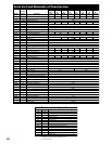
8
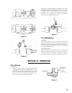
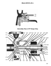
4. On S, M and L models, insert retaining ring (361A) into
groove in bearing housing (134A). Flat side of retaining ring
must be against bearing (112A). On X units, slide bearing end
cover (109A) and gasket (360C) on shaft. Ensure the “top” of
end cover (109A) lines up with the “top” of bearing housing
(134A), check scribe marks. If the bearing housing (134A) is
not installed properly (oil drain groove in bottom), oil will not
be able to drain from bearing causing it to overheat and fail
prematurely.
5. Oil inboard bearing seat on shaft. Slide inboard ball bearing
(168A) on shaft (122) as far as possible by hand. Continue as
in Step 1 above.
6. Place a small amount of O–ring lubricant on inside of
bearing frame (228A) at bearing housing (134A), at inboard
bearing seats (168A), on O-ring (496), and on inboard oil seal
(333A). Carefully slide shaft assembly into bearing frame. Do
not damage inboard oil seal (333A). Screw bearing housing
bolts (370C) about ” into bearing frame (228A) .
7. Slide deflector (123) on shaft (122).
8. If unit has packed stuffing box, place stuffing box cover (184)
against adapter (108), making sure that studs (370H) align with
proper holes in adapter. Replace nuts and firmly tighten. Slide
sleeve (if any) on shaft. Make sure grooves in end of sleeve
engage drive pin on shaft. Continue assembly at Step 10.
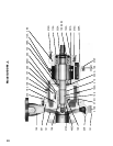
9. If unit has mechanical seal:
The following instructions refer to pumps equipped with
mechanical seals, either with or without sleeves.
If the unit has a single inside or double seal, a preliminary impeller
adjustment must be performed to assure proper positioning of
mechanical seal.
(1) Position sleeve (126), if any, on shaft (122) and engage
groove in sleeve with drive pin (469) on shaft. Place
stuffing box cover (184) against frame (228). Make sure
studs (370H) align with proper holes in frame. Firmly
tighten nuts or bolts.
(2) Screw impeller (101) with O-ring (412A) in place on shaft.
Make sure that shaft assembly extends through stuffing
box cover (184) so that the impeller will NOT contact
face of stuffing box cover.
(3) Using impeller adjusting bolts (370C and 370D), adjust
the impeller end clearance 0.015 with volute in place.
Mark shaft sleeve.
The following instructions are for three basic seal types:
Single Inside, Single Outside, and Double Seals. Refer to seal
manufacturer’s drawing seal type and positioning dimension.
Follow pertinent procedures.
a. Single Inside Seal
(1) Scribe the shaft (122) or shaft sleeve (126) lightly at
the face of the stuffing box.
(2) Remove the impeller and stuffing box.
(3) Assemble the gland (250) with gaskets and stationary
seat and slide the assembly over the shaft (122) or
shaft sleeve (126).
(4) Slide the rotary portion of the seal on the shaft (122)
(or shaft sleeve) (126) establishing its location from
the scribe line to the dimension as shown on the seal
manufacturer’s drawing. Tighten set screws.
(5) Reinstall the stuffing box cover and tighten. Do not
damage the seal parts.
(6) Reinstall the impeller with O-ring.
(7) Slide the gland assembly against the stuffing box and
tighten the nuts evenly. Do not damage the seal
parts.
(8) Refer to Step 12 for further assembly details.
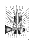
b. Double Seals
(1) Scribe the shaft (122) or shaft sleeve (126) lightly at
the face of the stuffing box.
(2) Remove the impeller and stuffing box.
(3) Assemble the gland (250) with gaskets and stationary
seat and slide the assembly over the shaft (122) or
shaft sleeve (126).
(4) Slide the rotary portion of the seal on the shaft (122)
or shaft sleeve (126) establishing its location from
the scribe line to the dimension as shown on the seal
manufacturer’s drawings. Tighten set screws.
(5) Place inboard stationary seat and gaskets into bottom
of stuffing box.
(6) Reinstall the stuffing box cover and tighten. Do not
damage seal parts.
(7) Reinstall the impeller with O–ring.
(8) Slide the gland assembly against the stuffing box and
tighten the nuts evenly. Do not damage seal parts.
(9) Refer to Step 12 for further assembly details.
c. Single Outside Seal
Preliminary impeller adjustment is not necessary with this
type of mechanical seal.
(1) If unit has shaft sleeve (126), slide on shaft (122)
and engage groove in sleeve with drive pin (469) on
shaft.
(2) Lubricate rotary portion of seal and slide on shaft
sleeve. Do not tighten set screws.
(3) Assemble gland (250), gaskets, and stationary seat
and slide assembly on shaft or sleeve.
(4) Place stuffing box cover (184) against frame making
sure that the studs (370H) align with the proper holes
in frame. Firmly tighten nuts.
(5) Screw impeller with O–ring on shaft making sure
impeller does not make contact with stuffing box
cover. If the impeller does hit, use impeller adjusting
cap screws to correct.
(6) Place gland assembly against face of stuffing box and
firmly tighten stud nuts.
(7) Slide rotary portion toward gland until it contacts
stationary seat. Compress the rotary. Tighten screws.
10. Screw impeller (101) with O–ring (412A) in place, on the
shaft (122).
11. On units with stuffing box packing (106), repack stuffing
box as outlined in Section II–F. Assemble gland stud nuts finger
tight.
12. Install and position coupling hub at scribe mark on shaft.