


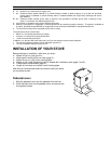
ULTRA FLAME DIRECT VENT GAS STOVE 21
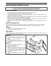
Burner
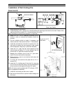
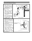
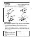
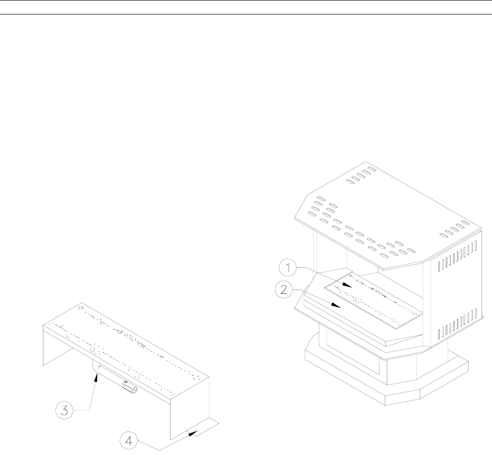
Removing the Burner
• Remove the glass front assembly. Lift out the grate and hearth insert around burner. Unscrew the burner
from the bottom of the combustion chamber,
• Slide the burner out from the ventury towards left. Get it out from the stove.
Burner Installation
• Get the burner back in place and push it towards right until the main orifice enters into the ventury.
• The o-ring gasket must be in place between the main orifice;
• Screw the burner back into the bottom of the combustion chamber.
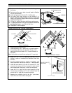
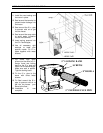
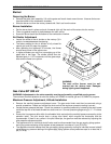
Air Shutter Adjustment
• Loosen the screw of the air shutter on the ventury (3) in
order to increase/decrease the opening.
• The factory setting for the air shutter is fully closed for
natural gas, and fully open for propane
• After operating the appliance 30 minutes, the flames
should have turned a nice yellow color.
• In higher altitudes you may find a smudging up of the
glass after a few days. The shutter should then be
adjusted open in 1/16” increments until the glass stays
clear and the flame turns yellow.
WARNING :
The main orifice (burner must be well
inserted into the ventury tube. Damages
during lighting could happened.
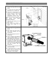
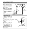
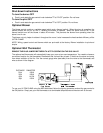
Gas Valve SIT 820 mV
WARNING: Adjustments to the valve assembly must be performed by a qualified service person.
The maximum manifold pressure is set at the factory at 3.5INWC for natural gas and 10.5INWC for propane.
Maximum Pressure Adjustment, Altitude Installation
• Remove the manifold pressure adjustment cover. The gas control knob must then be removed using a
special screwdriver. Rotate and reinstall the knob so that the maximum pressure reading is correct
• Locate the two pressure test taps. Check line pressure or manifold pressure by loosening the small screw
inside the tap with a flat-head screwdriver about one turn. Connect pressure gauge using a ¼” I. D. rubber
hose.
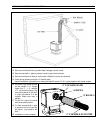
• Ensure the line pressure falls within the allowable limits and adjust the manifold pressure according to the
elevation table. The pilot should have a strong blue flame, which engulfs the thermopile and the
thermocouple. If there is any yellow in the pilot flame tips, the gas flow must be reduced by adjusting the
pilot pressure adjustment screw.
• The appliance and its individual shutoff valve must be disconnected from the gas supply piping system
during any pressure testing of that system at test pressures in excess of ½ psi (3.5 kPa);
• The appliance must be isolated from the gas supply piping system by closing its individual manual shutoff
valve during any pressure testing of the gas supply piping system at test pressures equal to or less that ½
psi (3.5 kPa);