


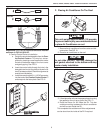
620515, 620525, 620526, 630515 & 630516 Installation Instructions
12
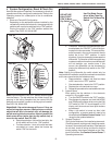
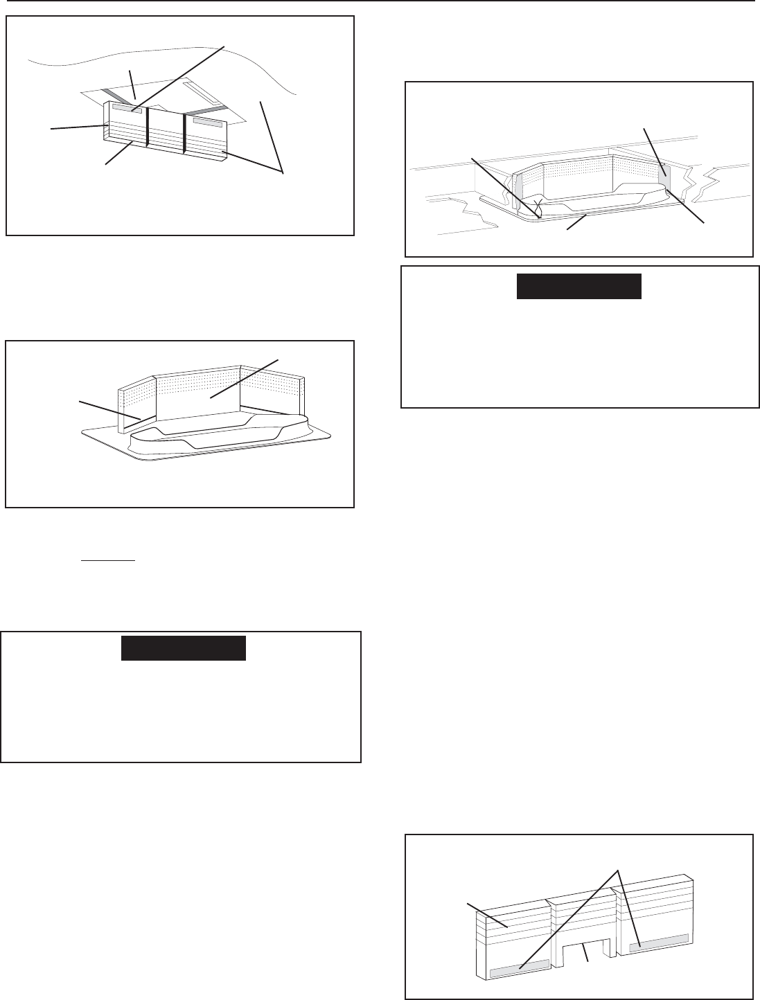
e. Use Aluminum foil tape (not supplied) to seal
the ends of the foam divider to the sides of the
opening. Make sure the area behind the flange
on the ceiling template is sealed. See FIG. 22.
2. Center Discharge Duct Application Installation
Note: If using non-center duct installation, go to Section 1.
"All Non-Center Duct Installations", on page 11.
Important: A duct adapter (not supplied) must be installed
between the unit discharge and the customer installed cen-
ter duct. This duct adapter must be approved by Dometic.
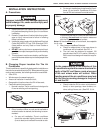
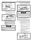
a. Check gasket alignment of the air conditioner
over the roof opening and adjust if necessary.
Unit may be moved from below by slightly lift-
ing and moving. See FIG. 13.
• Remove return air cover, ceiling template,
foam divider and air filter from the 3308120
carton.
• Locate the four (8" x 1/4-20) unit mounting
bolts, junction box cover and Romex con-
nector in the 3107180 bolt kit.
• Pull down the unit's electrical cord and fas-
ten the junction box with screws to the
framing in the front of the 14-1/4" x 14-1/4"
(±1/8") opening. See FIG. 14.
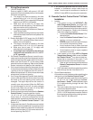
b. Installing Foam Divider
• Cut notch in the center section of the foam
divider to fit (approximately 2 x 8 inches)
snugly around duct. See FIG. 23.
Improper installation and sealing of foam di-
vider will cause the compressor to quick cycle
on the cold control. This may result in fuse or
circuit breaker opening and/or lack of cool-
ing.
CAUTION
If bolts are left loose there may not be ad-
equate roof seal or if over tightened, damage
may occur to the air conditioner base or ceil-
ing template. Tighten to specifications listed
in this manual.
CAUTION
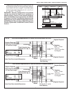
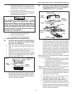
c. Install Ceiling Template
• Peel the paper off of the foam divider and
stick it in place on the center of the rear
flange of the return air opening on the ceil-
ing template. See FIG. 21.
d. Start each mounting bolt through the ceiling tem-
plate and up into the unit base pan by hand.
EVENLY tighten the three bolts to a torque
of 40 to 50 inch pounds. This will compress
the roof gasket to approximately 1/2". The
bolts are self locking so over tightening is
not necessary.
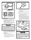
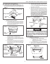
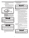
FIG. 20
Upside
Down
Foam
Divider
Base Pan
Ceiling
Place Foam Divider in
(14-1/4" x 14-1/4" (±1/8")
Ceiling Opening against
Base Pan Bottom
Do Not Peel Tape Off
Adhesive
Foam Divider Ceiling
Level (±1/4") Tear Off
Excess
FIG. 21
Foam Divider
Adhesive
Peel Off Paper - Center Divider - Stick To
Rear Flange On Ceiling Template
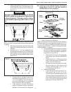
FIG. 22
Use Aluminum Foil Tape To Seal the
Foam Divider To The Sides of 14-1/4"
x 14-1/4" (±1/8") Ceiling Opening
Make Sure To Seal
Behind Flange
Route wires
through Slot
Catch Flange In Groove Of
Return Air Cover
FIG. 23
Foam
Divider
Mark And Cut 2” x 8”
Opening For Center Duct
Tape Covered
Adhesive