


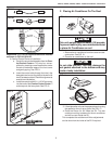
620515, 620525, 620526, 630515 & 630516 Installation Instructions
11
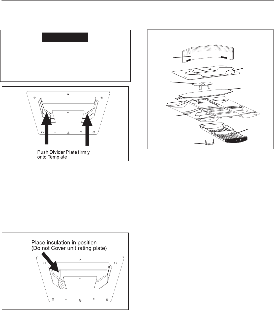
Improper installation and sealing of divider
plate will cause the compressor to quick cycle
on the cold control. This may result in fuse or
circuit breaker opening and/or lack of cool-
ing.
CAUTION
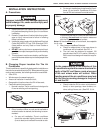
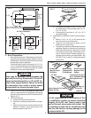
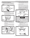
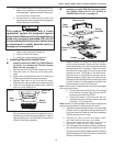
c. Place divider plate up to bottom of air condi-
tioner base pan firmly. The foam tape on the
divider plate must seal to bottom of base pan.
See FIG. 17.
Note: The adhesive on the insulation is extremely sticky.
Be sure the part is located where desired before pressing
into place.
d. With slight pressure then push the divider plate
against the double sided tape on the ceiling
template.
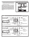
e. Locate the 1/8” x 7” x 18” self -adhesive insula-
tion supplied with the return air kit. Remove the
backing paper from the insulation and carefully
stick onto the ceiling template divider panel.
See FIG. 18.
• Excess width is intended to seal the di-
vider plate to the sides of the 14-1/4" x 14-
1/4" (±1/8") opening. This is to help pre-
vent cold air discharge from circulating into
the air conditioner return air opening.
• If the insulation is too high, stick excess
height of insulation to the air conditioner
base pan. Do not cover up unit rating plate.
Installing unit with 3308120 Genesis Air Filtration
System Return Air Kit. For unit with 3105007 or
3105935 Return Air Kit, see page 9.
1. All Non-Center Duct Installations
Note: The Genesis Air Filtration System can be installed on
units that use a center discharge duct through the 14-1/4" x
14-1/4" (±1/8") opening. Installing units with the center dis-
charge duct go to Section 1. "Center Discharge Duct Appli-
cation Installation", on page 6.
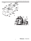
a. Check gasket alignment of the air conditioner
over the roof opening and adjust if necessary.
Unit may be moved from below by slightly lift-
ing and moving. See FIG. 13.
• Remove return air cover, ceiling template,
foam divider and air filter from the 3308120
carton.
• Locate the four (8" x 1/4-20) unit mounting
bolts, junction box cover and Romex con-
nector in the 3107180 bolt kit.
• Pull down the unit's electrical cord and fas-
ten the junction box with screws to the
framing in the front of the 14-1/4" x 14-1/4"
(±1/8") opening. See FIG. 14.
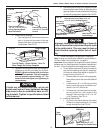
b. Installing Foam Divider
• Locate the foam divider and insert it cor-
ner to corner in the 14-1/4" x 14-1/4" (±1/
8") opening with the adhesive tape up (Do
not remove paper to expose adhesive). The
foam divider should be level with the ceiling
(±1/4"). Tear off the excess at the pre-cut
perforations in divider. See FIG. 20.
FIG. 17
FIG. 18
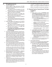
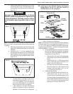
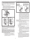
Micro-Therm Filter System
Micro-Therm
Filter
System
F
I
L
T
E
R
R
E
S
E
T
FILTER
RESET
C
L
E
AN
F
IL
T
ER
CLEAN
FILTER
Return Air
Cover
FIG. 19
Grill
Foam
Divider
Ceiling
Template
Slider
Filter
Handle
Genesis Air Filtration System
Return Air Kit