


620515, 620525, 620526, 630515 & 630516 Installation Instructions
8
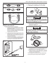
D. Wiring Requirements
1. 120 VAC Supply Line
Route a copper 12 AWG, with ground, 120 VAC
supply line from the time delay fuse or circuit breaker
box to the roof opening.
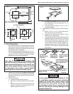
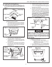
a. This supply line must be located in the front
portion of the 14-1/4" x 14-1/4" (±1/8") opening.
b. The power MUST be on a separate 20 Amp time
delay fuse or HACR circuit breaker.
c. Make sure that at least 15" of supply wire
extends into the roof opening. This ensures and
easy connection at the junction box.
d. Wiring must comply with all National, State and
Local Wiring Codes.
e. Use a steel sleeve and a grommet or equivalent
methods to protect the wire where it passes into
the opening.
2. Route a dedicated 12 VDC supply line (18-22 AWG)
from the RV's converter(filtered terminals) or
battery to the roof opening.
a. This supply line must be located in the front
portion of the 14-1/4" x 14-1/4" (±1/8") opening.
b. Make sure that at least 15" of supply wire
extends into the roof opening.
c. In a multiple zone installation, this wiring is
required in only one of the 14-1/4" x 14-1/4"
(±1/8") openings.
3. If a Remote Temperature Sensor is used, the con-
nector end must be routed from the sensor location
to the roof opening of the system which it will control.
Make sure that at least 15" of the sensor cable
extends into the roof opening. Refer to the Remote
Sensor Instructions for details of the installation.
4. If a furnace is to be controlled by the system, the two
furnace thermostat leads must be routed to the roof
opening of the air conditioner that will control it.
Make sure that at least 15" of the furnace thermostat
wires extend into the roof opening.
5. If an Energy Management System (load shed fea-
ture) is to be used with the control, two wires must
be routed to the roof opening of the zone to be
managed. The signal required for this function is
normally open relay contact. When the EMS calls
for the compressor to shut off, the relay contacts
should close. Make sure at least 15" of the EMS
wires extend into the roof opening.
6. Route a 4-conductor control cable from the Comfort
Control Center™ mounting position into the
14-1/4" x 14-1/4" (±1/8") roof opening. Make sure
that at least 15" of the wire extends into the roof
opening and 6" extend from the wall at the mounting
position of the Comfort Control Center™. See
Section E-2.
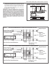
7. In the event that other Air Conditioners are installed
(additional zones) an additional 4-conductor control
cable must be routed to the other Air Conditioners.
Make sure that at least 15" of the wire extends into
the roof opening. See FIG. 27.
8. If an automatic generator start kit (AGS) will be
installed, a 4-conductor control cable must be
routed from the last air conditioner to location of
AGS kit. Follow AGS kit instructions for installation.
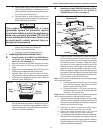
E. Dometic Comfort Control Center™ & Cable
Installation
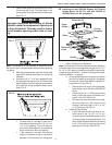
1. Location
a. If the system is to be used WITHOUT a Re-
mote Temperature Sensor, the proper loca-
tion of the Comfort Control Center™ is very
important to ensure that it will provide a comfort-
able RV temperature. Observe the following
rules when selecting a location:
• Locate the Comfort Control Center™ 54"
above the floor.
• Install the Comfort Control Center™ on a
partition, not on an outside wall.
• NEVER expose it to direct heat from lamps,
sun or other heat producing items.
• Avoid locations close to doors that lead
outside, windows or adjoining outside walls.
• Avoid locations close to supply registers
and the air from them.
b. If the system is to be used WITH a Remote
Temperature Sensor in ALL zones, the Com-
fort Control Center
TM
may be mounted any-
where that is convenient in the coach. Try to
avoid hard to reach and hard to see areas.
• Refer to the instructions provided with the
Remote Temperature Sensor for details
of installation.
c. A 3/8" diameter hole will be needed to route the
cable through the wall. See Section D-3.
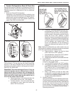
2. Control Cable Installation
A 4-conductor control cable must be routed from the
roof opening to the Comfort Control Center
TM.
a. Choose the shortest, most direct route from the
14-1/4" x 14-1/4" (±1/8") opening to the Com-
fort Control Center
TM
location selected. Leave
6" of cable extending through the wall. See
Section D-6.
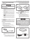
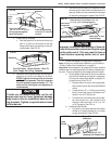
b. The control cable that should be used is a flat,
4-conductor telephone cable.
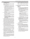
c. The control cable must be terminated with two
(2) RJ-11-6C4P telephone connectors. Refer to
the crimp tool manufacture for crimping instruc-
tions. See FIG. 8A, 8B and 8C.