


620515, 620525, 620526, 630515 & 630516 Installation Instructions
15
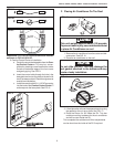
J. System Configuration, Reset & Check Out
Now that the system is installed, it is necessary to check all
operations and then configure the electronics. Refer to the
Operating manual for a description of the air conditioner
operation.
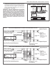
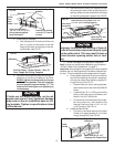
1. Electronic Control Kit Configuration
Depending on the equipment options installed by the
recreational vehicle manufacturer, the appropriate dip
switches will need to be switched to the "ON" position.
Placing the switch in the "ON" position selects that
option. See FIGS. 26, 26A & 26B.
d. Differential - differential is the temperature differ-
ence between the "ON/OFF" cycle of the ther-
mostat in the furnace mode. The normal differ-
ential is preset in the circuit board with the dip
switch set to the "OFF" position. In some
situations, it may be necessary to decrease the
differential. The location of the thermostat may
create a condition where the normal differential
will not maintain your comfort zone. If this
occurs, the differential can be shortened by
placing the differential dip switch to the "ON"
position.
Note: Setting the differential dip switch should only be
required when installation conditions are less than desirable
and is not covered under the limited warranty.
e. Stage selection - stage is not used on these
units. Leave in the "OFF" position.
f. Gen start selection - leave in the "OFF" position.
g. Replace the unit electrical box cover.
h. Repeat this procedure for each additional zone.
2. System Reset
After setting the dip switches in the electronic
control kit, do a system reset.
a. Turn the ON/OFF switch to the "OFF" position.
b. Simultaneously depress and hold the MODE
and ZONE push-buttons while turning the ON/
OFF switch to "ON". FF should appear in LCD
display until the mode and zone push-buttons
are released.
c. When a dip switch is turned on after initial
configuration, a system reset will need to be
done before the Comfort Control Center™ will
recognize the updated selection.
3. System Checkout
Verify that all features of the installed system work.
Check fan speeds, cooling mode, heat pump mode,
furnace (if connected) and heat strip. If the features
do not work, check all wiring and confirm that the
correct options have been selected on the Elec-
tronic Control Box. See Comfort Control Center™
Operating Instructions.
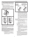
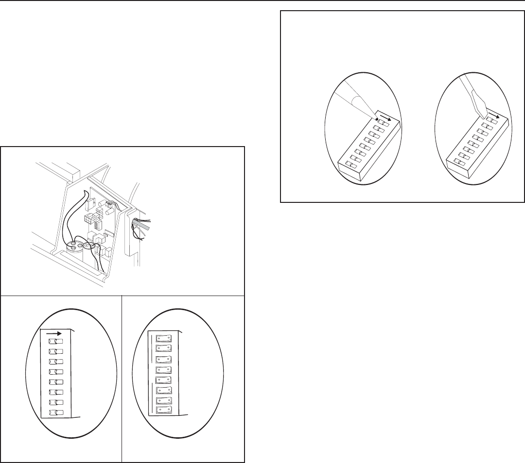
Note: Dip switches are in the "OFF" position when shipped
from the factory. The dip switches are visible through the
opening in the ceiling template into the control box.Dip
switches can be either a rocker or sliding style of a switch.
See FIGS. 26, 26A & 26B.
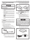
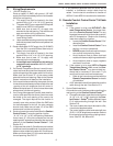
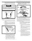
Important: Dip switch damage will occur if they are
not set in the proper manner. A ball point pen or similar
object that will slip in the switch slot, can damage the
switch causing loss of connection. Use only a small flat
blade screw driver (wider than the dip switch slot) to
move the dip switch. See FIG. 26C.
b. Heat strip selection: Units with a heat strip, the
#1 dip switch will be in the "ON" position.
c. Furnace selection - when a furnace has been
connected to a zone, place the furnace dip
switch "ON" for that zone.
12 345
ON
678
12 345
ON
678
FIG. 26C
Not Correct
Use Flat Blade Screw-
driver Wider Than Dip
Switch Slot To Move Dip
Switch
DO NOT USE
BALL POINT
PEN To Move
Dip Switch
Correct
FIG. 26
12 345
HEAT STRIP
ZONE 2
ZONE 3
ZONE 4
FURNACE
ON
678
DIFFERENTIAL
STAGE
GEN START
SLIDE
SWITCH
SLIDE
SWITCH
1
2
3
4
5
HEAT STRIP
ZONE 2
ZONE 3
ZONE 4
FURNACE
OPEN
6
7
8
DIFFERENTIAL
STAGE
GEN START
ROCKER
SWITCH
ROCKER
SWITCH
FIG. 26A FIG. 26B