


13
one black), noting all of their original positions.
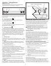
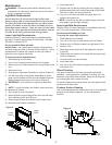
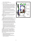
Turn the top panel over and while supporting the 5.
Heater Assembly and panel in one hand, remove the
ve (5) heater mounting screws, noting the center
screw is of a larger diameter (Figure 18).
Separate the Heater Assembly from the top panel.6.
Properly orient the new Heater Assembly and re-7.
connect all of the wiring connections.
Reassemble in the reverse order as above.8.
Power Cord Replacement
WARNING: If unit was operating prior to servicing allow
at least 5 minutes for light bulbs and heating element to
cool off to avoid accidental burning of skin.
WARNING: Disconnect power before attempting any
maintenance or cleaning to reduce the risk of electric
shock or damage to persons.
Tools Required: Phillips head Screwdriver
Remove the rebox from the mantel.1.
Lay unit on its back.2.
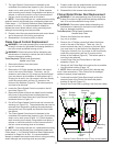
Remove the 12 Philips screws that fasten the bottom 3.
cover to the rest of the rebox. There are: two (2)
screws on each side; two (2) screws on the back panel
(you may have to tip the bottom of the replace up if it
is laying on its back), four (4) screws in the front directly
under the control panel; and two (2) screws on the
bottom of the replace (Figure 8). The bottom panel is
now free to be removed.
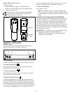
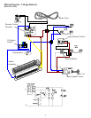
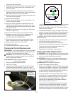
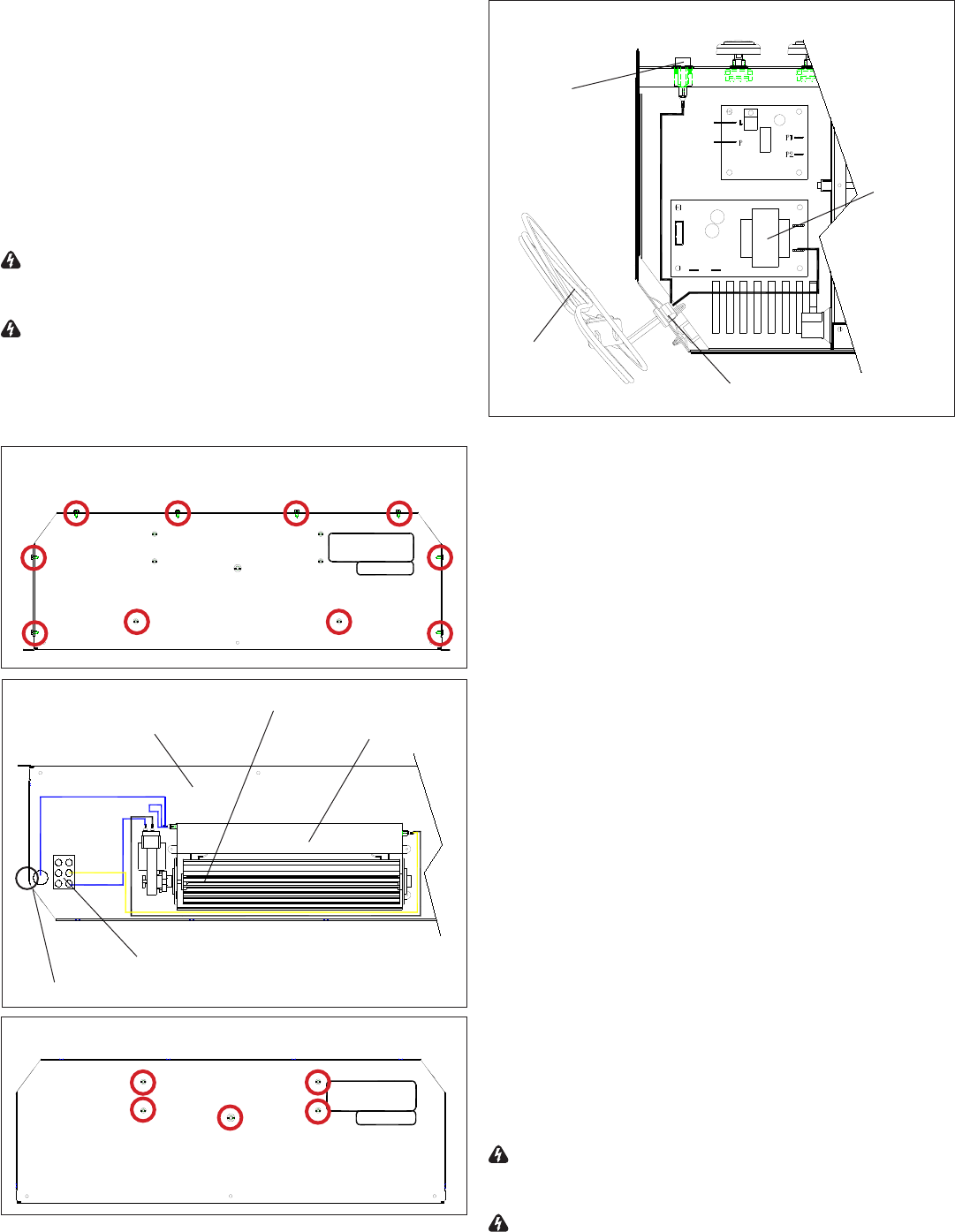
Locate and disconnect the two (2) power cord wire 4.
connections: one from the middle of the three (3)
connectors on the On/Off Switch; the other on the
Flame Speed Control board, noting their original
locations (Figure 19).
Using pliers, squeeze the sides of the plastic wire 5.
clamp from inside the bottom assembly area and push
it through the chassis.
Release clamp from power cord and remove power 6.
cord.
Install replacement power cord through opening in the 7.
chassis and secure with clamp.
Reassemble in the reverse order as above.8.
Remote Control Replacement (If
Applicable)
Tools Required: Phillips head Screwdriver
Flat Head Screwdriver
Needle Nose Pliers
Remote Controls require no replacement procedure
however, an initialization procedure may need to be
followed. Refer to the Operation Section for the Remote
Initialization Procedure.
WARNING: If unit was operating prior to servicing allow
at least 5 minutes for light bulbs and heating element to
cool off to avoid accidental burning of skin.
WARNING: Disconnect power before attempting any
maintenance or cleaning to reduce the risk of electric
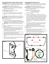
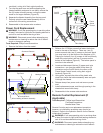
Figure 16
Screws to Remove
Figure 17
Top Panel
Heater Assembly
Terminal Block
Wires Leading to Bottom Assembly
Heating Element
Figure 19
Wire Clamp
Power
Cord
On/Off
Switch
Flame
Speed
Control
Figure 18