


11
Properly orient the new potentiometer and control board 8.
and re-connect all of the wiring connections.
Reassemble in the reverse order as above.9.
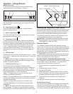
Flicker Motor/Flicker Rod Replacement
WARNING: If unit was operating prior to servicing allow
at least 5 minutes for light bulbs and heating element to
cool off to avoid accidental burning of skin.
WARNING: Disconnect power before attempting any
maintenance or cleaning to reduce the risk of electric
shock or damage to persons.
Tools Required: Phillips head Screwdriver
Needle Nose Pliers
Remove the rebox from the mantel.1.
Lay unit on its back.2.
Remove the 12 Philips screws that fasten the bottom 3.
cover to the rest of the rebox. There are: two (2)
screws on each side; two (2) screws on the back panel
(you may have to tip the bottom of the replace up if it
is laying on its back), four (4) screws in the front directly
under the control panel; and two (2) screws on the
bottom of the replace (Figure 8). The bottom panel is
now free to be removed.
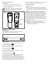
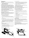
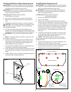
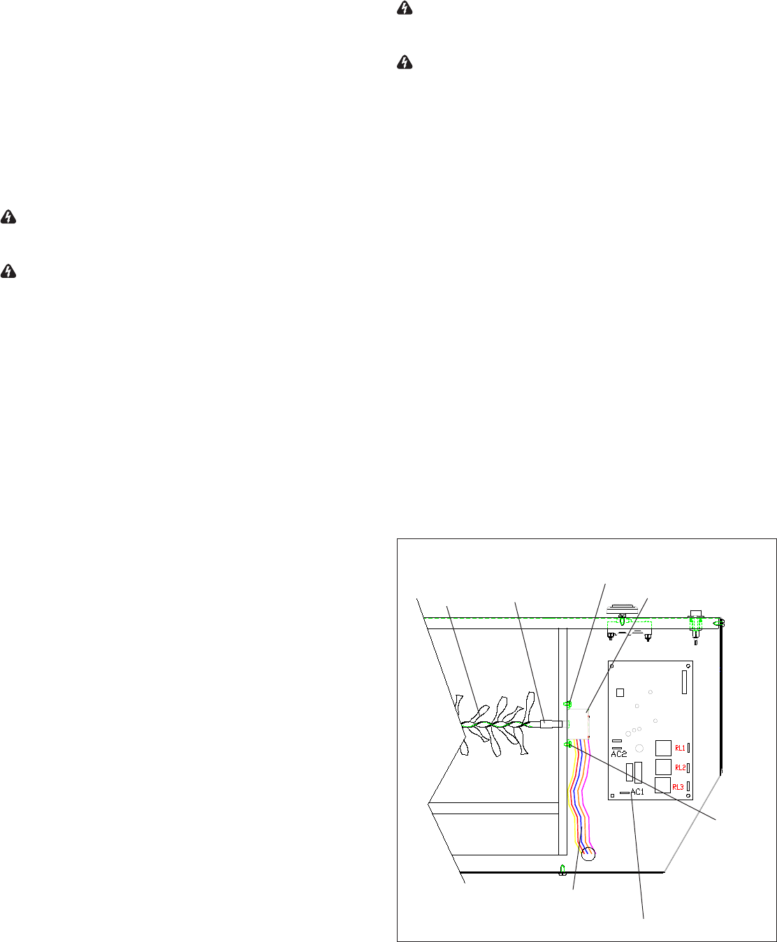
Locate Flicker Rod and Flicker Motor in the base 4.
assembly (Figure 13).
Gently pull the Flicker Rod to the right as far as possible 5.
into the rubber bushing (Figure 13).
!
NOTE: When removing the Flicker Rod, damage may
occur if bent excessively. If the Flicker Rod is damaged,
replace to ensure proper operation.
Cautiously bend the Flicker Rod enough so that the 6.
remaining end of the Flicker Rod clears the plastic
bushing on the left (Figure 13).
Remove the Flicker Rod by pulling it free from the rubber 7.
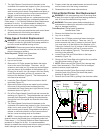
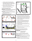
The Light Dimmer Control board is fastened to the 7.
underside of the ember bed support by four (4) mounting
studs, one in each corner (Figure 11). Either squeeze
each mounting stud’s clasp, using needle nose pliers, to
release, or use side cutters to cut and remove each of
the four corner mounting studs on the board.
!
NOTE: If mounting studs are cut, replacement mounting
studs will need to be inserted from underneath ember bed.
Follow steps 1 - 5 of Partially Reective Glass Replacement
procedure to do this. It is recommended to attempt to
release the control board without cutting mounting studs,
although new mounting studs are provided.
Properly orient the new potentiometer and control board 8.
and re-connect all of the wiring connections.
Reassemble in the reverse order as above.9.
Flame Speed Control Replacement
WARNING: If unit was operating prior to servicing allow
at least 5 minutes for light bulbs and heating element to
cool off to avoid accidental burning of skin.
WARNING: Disconnect power before attempting any
maintenance or cleaning to reduce the risk of electric
shock or damage to persons.
Tools Required: Phillips head Screwdriver
Needle nose Pliers
Remove the rebox from the mantel.1.
Lay unit on its back.2.
Remove the 12 Philips screws that fasten the bottom 3.
cover to the rest of the rebox. There are: two (2)
screws on each side; two (2) screws on the back panel
(you may have to tip the bottom of the replace up if it
is laying on its back), four (4) screws in the front directly
under the control panel; and two (2) screws on the
bottom of the replace (Figure 8). The bottom panel is
now free to be removed.
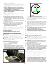
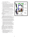
Locate the Flame Speed Control mounted on the left 4.
hand side (Figure 12).
Remove the white and blue wire leads from the bottom, 5.
left corner of the control board and feed the wires
underneath the Flame Speed and Light Dimmer Control
boards as shown in Figure 12.
Pull off the Flame Speed Control knob and unscrew the 6.
retaining nut (Figure 12). The potentiometer can now be
removed from the panel by pushing the potentiometer
through the front of the panel and removed from inside
the cabinet.
The Flame Speed Control board is fastened to the 7.
underside of the ember bed support by four (4) mounting
studs, one in each corner (Figure 12). Either squeeze
each mounting stud’s clasp, using needle nose pliers, to
release, or use side cutters to cut and remove each of
the four corner mounting studs on the board.
!
NOTE: If mounting studs are cut, replacement mounting
studs will need to be inserted from underneath ember bed.
Follow steps 1 - 5 of Partially Reective Glass Replacement
procedure on Page 9 to do this. It is recommended to
attempt to release the control board without cutting mounting
studs, although new mounting studs are provided.
Figure 13
Flicker
Rod
Flicker
Motor
5 Colour
Cable
Mounting
Screw
Rubber
Bushing
Mounting
Screw
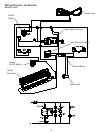
Remote Control Receiver may or may not be present