


10
Heater On/Off Switch Replacement
WARNING: If unit was operating prior to servicing allow
at least 5 minutes for light bulbs and heating element to
cool off to avoid accidental burning of skin.
WARNING: Disconnect power before attempting any
maintenance or cleaning to reduce the risk of electric
shock or damage to persons.
Tools Required: Phillips head Screwdriver
Flat head Screwdriver
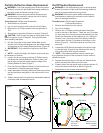
Remove the rebox from the mantel.1.
Lay unit on its back.2.
Remove the 12 Philips screws that fasten the bottom 3.
cover to the rest of the rebox. There are: two (2) screws
on each side; two (2) screws on the back panel (you may
have to tip the bottom of the replace up if it is laying on
its back), four (4) screws in the front directly under the
control panel; and two (2) screws on the bottom of the
rebox (Figure 8). The bottom panel is now free to be
removed.
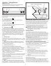
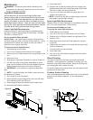
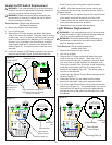
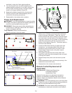
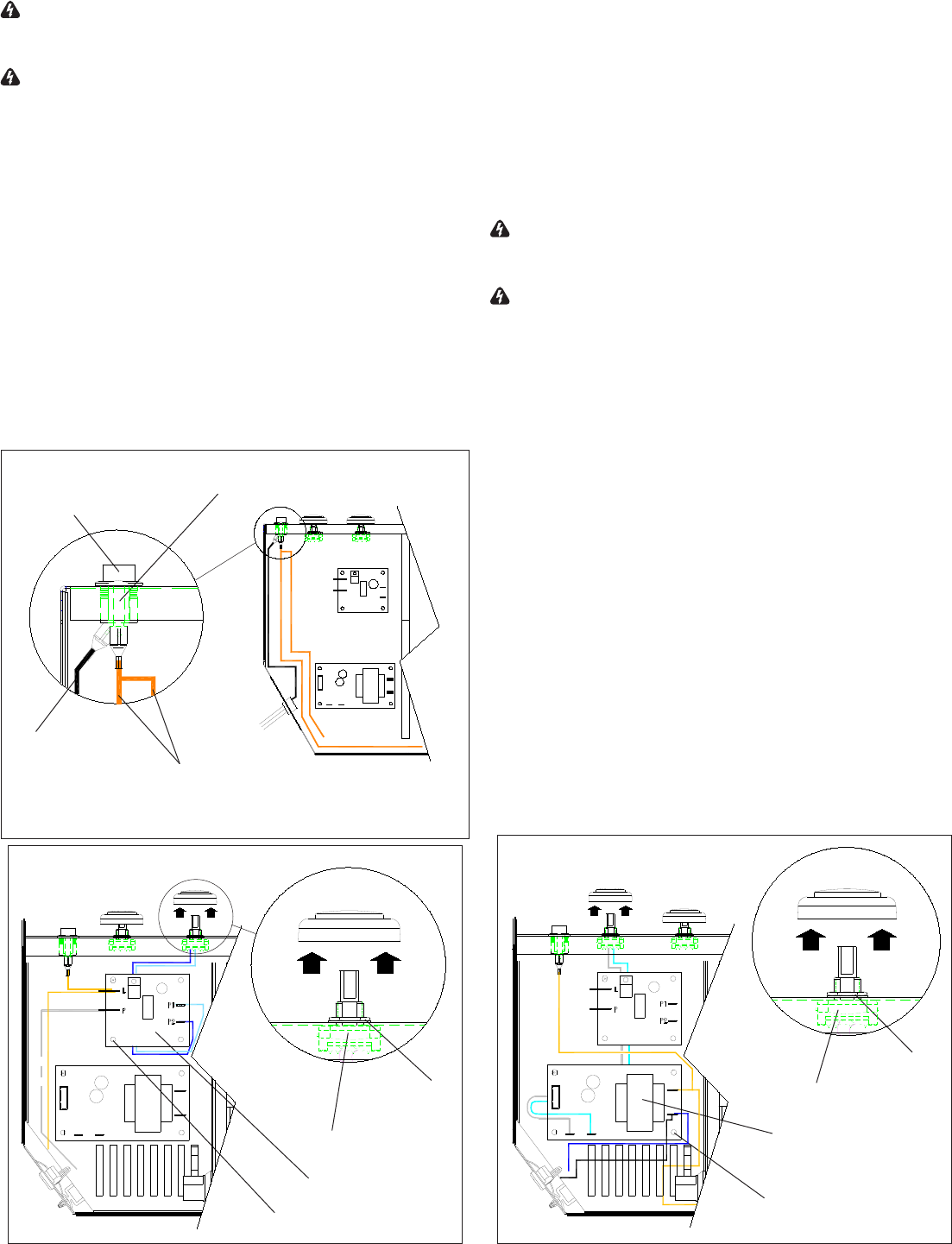
Locate the Heater On/Off Switch mounted to the control 4.
panel on the left side (Figure 10) and disconnect the
three (3) wiring clips noting their original locations.
!
NOTE: A at head screwdriver can be used to gen-
tly pry between the end of the connector and the switch to
release the wires.
Depress the two (2) retainer clips on the top and bottom 5.
of the switch and push the switch out of the cover.
Properly orient the new switch and re-connect all of the 6.
wiring clips and connections as before.
Reassemble in the reverse order as above.7.
Light Dimmer Replacement
WARNING: If unit was operating prior to servicing allow
at least 5 minutes for light bulbs and heating element to
cool off to avoid accidental burning of skin.
WARNING: Disconnect power before attempting any
maintenance or cleaning to reduce the risk of electric
shock or damage to persons.
Tools Required: Phillips head Screwdriver
Needle nose Pliers
Remove the rebox from the mantel.1.
Lay unit on its back.2.
Remove the 12 Philips screws that fasten the bottom 3.
cover to the rest of the rebox. There are: two (2)
screws on each side; two (2) screws on the back panel
(you may have to tip the bottom of the replace up if it
is laying on its back), four (4) screws in the front directly
under the control panel; and two (2) screws on the
bottom of the replace (Figure 8). The bottom panel is
now free to be removed.
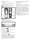
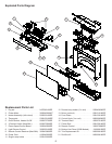
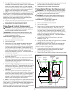
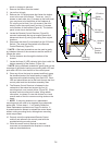
Locate the Light Dimmer Control Board mounted on the 4.
left side (Figure 11).
Disconnect the two (2) wire leads from the control 5.
board’s left hand side, noting their original locations.
Pull off the Light Dimmer Control knob and unscrew the 6.
retaining nut (Figure 11). The potentiometer can now be
removed from the panel by pushing the potentiometer
through the front of the panel and removed from inside
the cabinet.
Figure 10
Retainer Clips
Heater On/Off
Switch
Black wire from
top terminal to
Power Cord
Piggy-back dark orange wires
from bottom terminal (closest
to bottom of rebox)
Figure 11
Light Dimmer
Control Board
Retaining
Nut
Potentiometer
Mounting Studs (4)
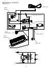
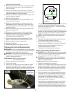
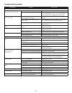
Figure 12
Retaining
Nut
Potentiometer
Mounting Studs (4)
Flame Speed
Control Board