


www.fmiproducts.com
116986-01H24
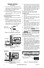
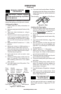
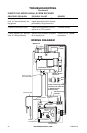
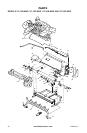
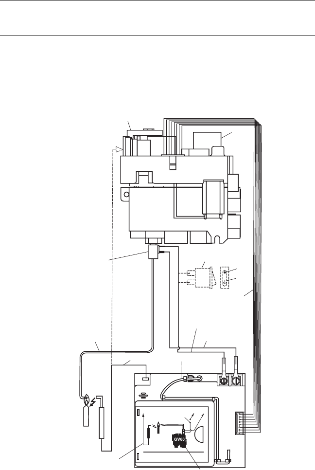
WIRING DIAGRAM
SPARK
SPARK
Pilot
4 AA Batteries
ON/OFF
Switch
Thermocurrent
Interrupter Block
SW
SW
TC
TC
Battery
Compartment
MA
GR
MO
SW
PANEL
Receiver
Antenna
Ignition Cable
Thermocouple
Thermocurrent
Interrupter Block
Combination Control
ON/OFF Switch
(Optional)
OFF
ON
8 Wire Connecting Cable
Thermocurrent Cable #2
or ON/OFF Switch
Soldered Cable
Thermocurrent
Cable #1
Motor
Knob
MAN Knob
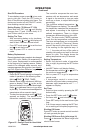
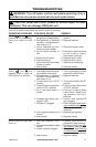
TROUBLESHOOTING
Continued
Battery nearly down. (When
signal appears the rst time ap-
proximately 10 ignitions left)
Cable is not connected, ON/OFF
switch is in OFF position
Ignition not successful, possible
air in supply line
REMEDY
Replace battery
Connect cables
Switch to ON. Repeat
procedure
Long signals (0.8 second
tone, 0.2 second break) dur-
ing ignition
5 second continuous tone
5 short signals (8.2 second
tone, 0.2 second break)