


www.fmiproducts.com
116986-01H20
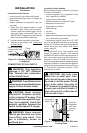
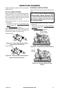
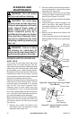
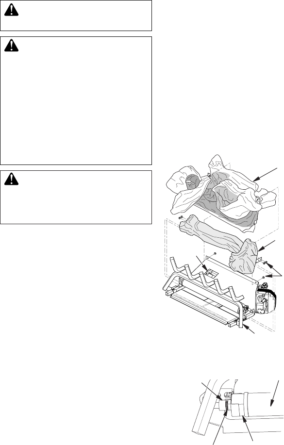
Figure 26 - Injector Holder on Front
Burner Tube
Burner Tube
Primary Air
Inlet Opening
Injector
Holder
Injector
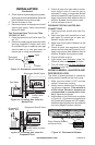
Figure 25 - Removing Front Log to Clean
Front Burner
Main Log
Assembly
Front Log
Assembly
Screws
Base
Assembly
Cleaning
Access
CLEANING AND
MAINTENANCE
WARNING: Turn off heater
-
-
INLET HOLE
The primary air inlet holes allow the proper
amount of air to mix with the gas. This pro-
vides a clean burning ame. Keep these holes
clear of dust, dirt, lint and pet hair. Clean these
air inlet holes prior to each heating season.
Blocked air holes will create soot. We recom-
mend that you clean the unit every 3 months
during operation and have heater inspected
yearly by a qualied service person.
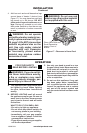
We also recommend that you keep the burner
tube clean and free of dust and dirt. We rec-
ommend using compressed air no greater
than 30 PSI. Your local computer store,
hardware store or home center may carry
compressed air in a can. If using compressed
air in a can, please follow the directions on the
can. If you don't follow directions on the can,
you could damage the pilot assembly.
Before cleaning, shut off unit, including pilot.
Allow unit to cool for at least 30 minutes. You
will need to remove the front log to access
front burner.
1. Remove two screws from back of unit
that attach main log assembly to base
assembly (see Figure 25).
2 . Remove screws from left and right side of
front log assembly to remove from base
assembly (see Figure 25).
3. Inspect burner and primary air inlet holes
on injector holder of each burner for dust
and dirt (see Figures 25 and 26).
4. Blow air through the ports/slots and holes
in the burner.
5. Check the injector holder located at the
end of the burner tube again. Remove
any large particles of dust, dirt, lint or pet
hair with a soft cloth or vacuum cleaner
nozzle.
6. Blow air into the primary air holes on the
injector holder.
7. In case any large clumps of dust have now
been pushed into the burner repeat steps
5 and 6.