


www.fmiproducts.com
116986-01H14
INSTALLATION
Continued
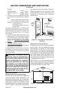
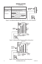
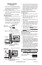
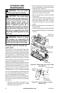
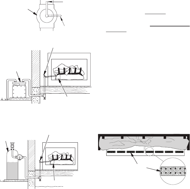
Figure 13 - Equipment Shutoff Valve
Open
Closed
Equipment
Shutoff Valve
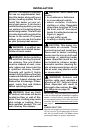
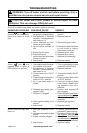
Figure 15 - Checking Gas Joints for
Propane/LP Gas
Control Valve Location
Propane/LP
Supply Tank
Equipment Shutoff Valve
Figure 14 - Checking Gas Joints for
Natural Gas
Gas Meter
Equipment Shutoff Valve
Control Valve
Location
4. Check all joints of gas supply piping system.
Apply noncorrosive leak detection uid to all
joints. Bubbles forming show a leak.
5. Correct all leaks at once.
6. Reconnect heater and equipment shutoff
valve to gas supply. Check reconnected
ttings for leaks.
1. Close equipment shutoff valve (see Fig-
ure 13).
2. Pressurize supply piping system by either
opening propane/LP supply tank valve
for propane/LP gas or opening main gas
valve located on or near gas meter for
natural gas or using compressed air.
3. Check all joints from gas meter to equip-
ment shutoff valve for natural gas or
propane/LP supply to equipment shutoff
valve for propane/LP (see Figure 14 or 15).
Apply noncorrosive leak detection uid to
all joints. Bubbles forming show a leak.
4. Correct all leaks at once.
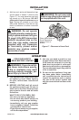
CONNECTIONS
1. Open equipment shutoff valve (see Fig-
ure 13).
2. Open main gas valve located on or near
gas meter for natural gas or open pro-
pane/LP supply tank valve.
3. Make sure control knob of heater is in the
OFF position.
4. Check all joints from equipment shutoff
valve to control valve (see Figure 14 or 15).
Apply noncorrosive leak detection uid to
all joints. Bubbles forming show a leak.
5. Correct all leaks at once.
6. Light heater (see Operation, page 15).
Check all other internal joints for leaks.
7. Turn off heater (see To Turn Off Gas to
Appliance, page 18).
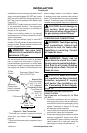
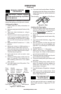
The effect of glowing embers is created by
placing ember material on the front burner.
1. Make sure the heater is OFF and has
cooled if it has been running.
2. Gently remove embers from the bag us-
ing gloves or tweezers.
-
Separate the pieces.
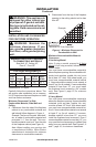
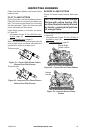
3. Add embers to front at burner as shown
in Figure 16. (12 pieces are supplied with
24" models and 8 pieces with 18" models.)
Additional glowing effect can be achieved
by fraying edges of ember material.
Figure 16 - Placement of Embers
Place Glowing Embers
on Burner Ports