


www.desatech.com
113109-01C 11
INSTALLATION
Continued
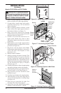
10. If blower is installed, route blower electrical cord
through access holes in either side of replace.
Note: Bushing may be moved if necessary. Plug
electrical cord into electrical outlet.
11. Carefully insert replace into cabinet mantel.
Be careful not to scratch or damage hearth
base, cabinet mantel or any laminate trim on
hearth base (VYGF models only). Remove
protective material from top of hearth base and
from front of replace (if any). Note: You can
secure replace to hearth or oor. Open lower
louver. Locate screw holes in bottom of base.
Tighten wood screws through these holes and
into hearth or oor.
12. Check all gas connections for leaks. See
Checking Gas Connections, page 15.
BUILT-IN FIREPLACE INSTALLATION
Built-in installation of this replace involves
installing replace into a framed-in enclosure.
This makes the front of replace ush with wall.
If installing a mantel above the replace, you
must follow the clearances shown in Figure 20,
page 13. Follow the instructions below to install
the replace in this manner.
Actual Framing
Height 32
3
/8" 33"
Front Width 34
5
/16" 35
1
/2"
Depth 16
11
/16" 17
3
/4"
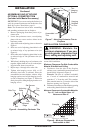
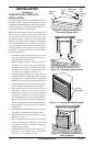
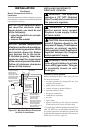
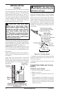
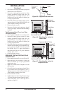
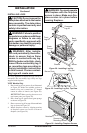
1. Frame in rough opening. Use dimensions shown
in Figure 13 for the rough opening. If installing
in a corner, use dimensions shown in Figure 14
for the rough opening. The height is 33" which
is the same as the wall opening above.
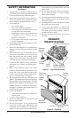
2. If using blower, install and properly ground
GA3555, three-prong 120 volt electrical out-
let, in replace. Follow instructions included
in kit (see Accessories, page 38).
3.
Install gas piping to replace location. This in-
stallation includes an approved exible gas line
(if allowed by local codes) after the equipment
shutoff valve. The exible gas line must be the
last item installed on the gas piping. See Install-
ing Gas Piping to Fireplace Location, page 13.
4. Carefully set replace in front of rough opening
with back of replace inside wall opening.
5. Plug electrical cord into electrical outlet
installed in step 2.
6. Carefully insert replace into rough opening.
7. Attach exible gas line to gas supply. See Con-
necting Fireplace to Gas Supply, page 14.
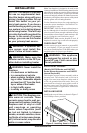
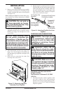
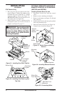
8. Attach replace to wall studs using nails or
wood screws through holes in nailing ange
(see Figure 15).
9. Check all gas connections for leaks. See
Checking Gas Connections, page 15.
10. Install perimeter trim after nal nishing and/or
painting of wall (see Figure 7, page 9).
35
1
/
2
"
17
3
/
4
"
33"
Figure 13 - Rough Opening for Installing
in Wall
39
3
/
8
"
27
7
/
8
"
55
5
/
8
"
35
1
/
2
"
Figure 14 - Rough Opening for Installing
in Corner
Figure 15 - Attaching Fireplace to Wall
Studs
Nailing
Flanges
Nails or
Wood
Screws