


www.desatech.com
113109-01C12
INSTALLATION
Continued
-
-
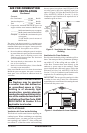
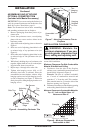
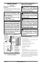
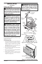
1. Frame in rough opening. Use dimensions
shown in Figure 16 for the rough opening.
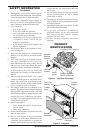
2. If using blower, install wiring and properly
ground the three-prong, 120 volt electrical
outlet in replace.
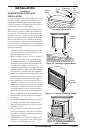
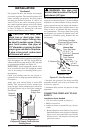
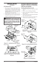
3. Before replacing bottom of rebox, install
duplex outlet to the right support bracket in
the bottom of rebox (see Figure 17).
4. Route wires from electrical box through
smallest hole in outer casing using strain relief
tting provided (see Figure 17).
5. Connect wires from the electrical box to
duplex outlet. Match wire colors to those
indicated on duplex outlet. Be sure to connect
ground wire.
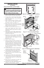
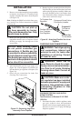
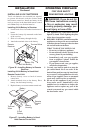
6. Install shield to end of right support bracket
and behind the rebox wrapper with 2 screws
provided (see Figure 18).
7. Plug blower cord into duplex outlet. No te:
On thermostat model replaces, route power
cord to the back of the replace to clear
thermostat valve.
8. Replace bottom of rebox.
9. Install gas piping to replace location. This
installation includes an approved exible
gas line (if allowed by local codes) after the
equipment shutoff valve. The exible gas line
must be the last item installed on the gas pip-
ing. See Installing Gas Piping to Fireplace
Location, page 13.
10. Carefully set replace in front of rough opening
with back of replace inside wall opening.
11. Attach exible gas line to gas supply. See Con-
necting Fireplace to Gas Supply, page 14.
12. Plug electrical cord into electrical outlet
installed in step 2.
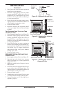
13. Carefully insert replace into rough opening.
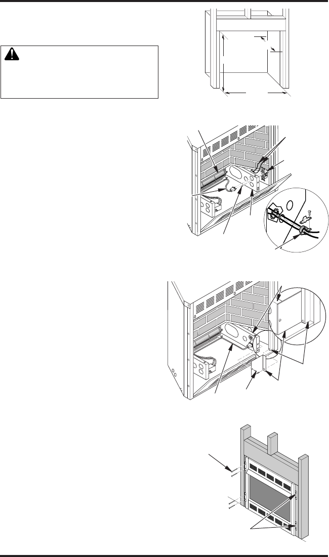
14. Attach replace to wall studs using nails or
wood screws through holes in nailing ange
(see Figure 19).
15. Check all gas connections for leaks. See
Checking Gas Connections, page 15.
16. Install brass trim after nal nishing and/or
painting of wall (see Figure 7, page 9).
35
1
/2"
17
3
/4"
33"
Figure 16 - Rough Opening for Installing
in Wall
Blower
Support
Bracket
Cable from
Electrical
Source
Duplex
Outlet
Screw
Blower
Power
Cord
Strain
Relief Fitting
Figure 17 - Connecting Duplex Outlet
Figure 19 - Attaching Fireplace to Wall Studs
Nailing
Flanges
Nails or
Wood
Screws
Screws
Support Bracket
Firebox
Wrapper
Power
Cord
Figure 18 - Attaching Fireplace to Wall Studs