


8
105647
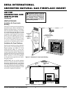
UNVENTED NATURAL GAS FIREPLACE INSERT
DESA INTERNATIONAL
For more information, visit www.desatech.com
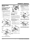
INSTALLATION
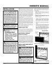
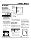
CLEARANCES
WARNING: Maintain the mini-
mum clearances. If you can, pro-
vide greater clearances from
floor, ceiling, and adjoining wall.
INSTALLATION
Continued
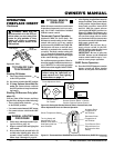
4. Using Phillips screwdriver, remove
four screws attaching brass louver. In-
stall one Phillips head screw (included
with kit) in each side (see Figure 7).
5. Align top panel screw holes. Install four
Phillips screws, do not tighten.
6. For model GS43, align six screw holes
in side panels with holes in top panel
(see Figure 9). For model GS38, align
two screw holes in side panels with
holes in top panel (see Figure 9). Insert
and tighten screws.
7. Carefully inspect fireplace surround as-
sembly. Make sure each part fits prop-
erly. Firmly tighten all screws installed
during assembly.
CAUTION: Do not overtighten.
Metal can bend, warp, or break
under excessive strain.
8. Remove three pieces of brass trim from
packaging.
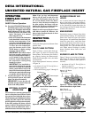
9. Locate four brass screws, two adjust-
ing plates with set screws, and two
shims in the brass hardware packet.
10. Align shim under adjusting plate as
shown in Figure 10.
11. Slide one end of adjusting plate/shim
in slot of top brass trim (see Figure 10).
12. Slide other end of adjusting plate/shim
in slot on mitered edge of side brass
trim (see Figure 10).
13. While firmly holding edges of brass
trim together, tighten both set screws
on the adjusting plate with slotted
screwdriver.
14. Repeat for other side.
15. Line up holes in brass trim with holes
on side panels of fireplace surround
assembly. Attach with brass-plated
screws.
16. Move fireplace insert and surround as-
sembly to masonry fireplace opening.
Make sure fireplace insert and surround
assembly fit properly.
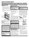
Figure 7 - Remove Brass Louver
Brass Louver
Phillips Screws
Top Surround Panel
Louver Screw Holes
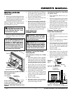
Figure 9 - Attaching Side Panels to Top
Panel (GS43 Pictured)
Top Panel
Side Panel
Figure 8 - Attaching Top Surround Panel
Phillips
Screws (4)
Top Brass
Trim
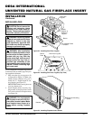
Figure 10 - Assembling Brass Trim
Slot
Side Brass
Trim
Set Screws
Adjusting
Plate
Slot
Mitered
Edge
Shim
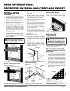
Figure 11 - Installing Hood to Firebox
INSTALLING HOOD
Install hood to top of firebox as shown in
Figure 11. Use 7 Phillips screws provided.
Screws
Carefully follow the instructions below. This
will ensure safe installation.
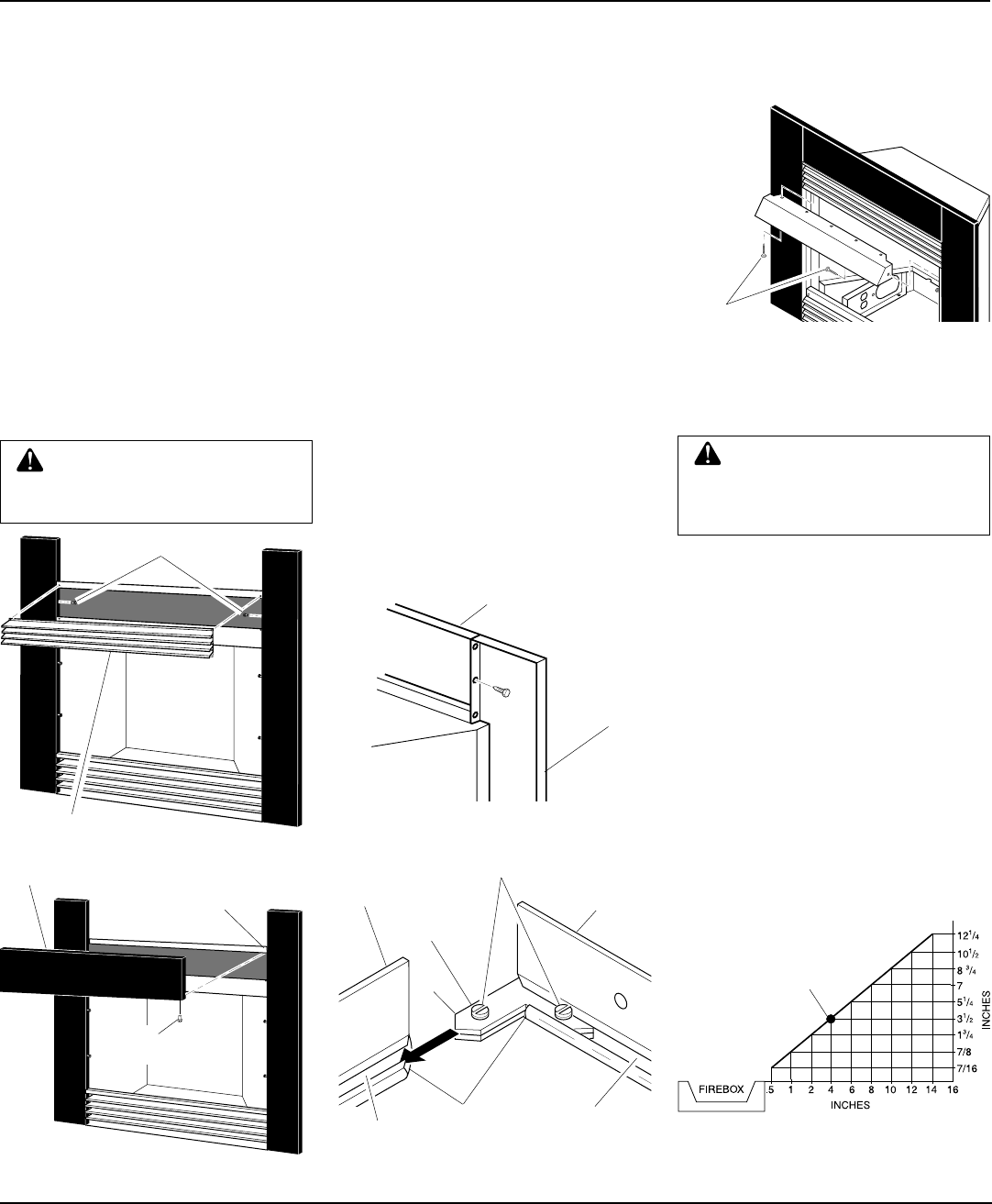
Minimum Clearances For Side
Combustible Material, Side Wall,
and Ceiling
A. Clearances from the side of the fireplace
cabinet to any combustible material and
wall should follow diagram in Figure 12.
Example:
The face of a mantel, bookshelf,
etc. is made of combustible material and
protrudes 3
1
/2" from the wall. This com-
bustible material must be 4" from the side
of the fireplace opening (see Figure 12).
B. Clearances from the top of the fireplace
opening to the ceiling should not be less
than 42 inches.
Figure 12 - Minimum Clearance for
Combustible to Wall
*Minimum 16 inches from Side Wall
*
Example