


20
105647
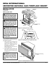
UNVENTED NATURAL GAS FIREPLACE INSERT
DESA INTERNATIONAL
For more information, visit www.desatech.com
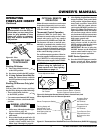
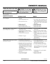
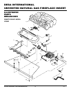
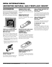
Red
Variable
Fan Switch
Fan Switch
(N.O.)
Green
White
On
110/115
V.A.C.
Blower
Motor
Black
Off
1
2
Black
Blue
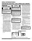
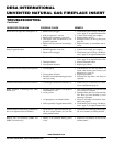
SPECIFICATIONS
VI33NR Remote Ready Insert
Btu (Variable) 20,000/30,000
Type Gas Natural Gas Only
Ignition Piezo
Pressure Manifold 3.5" W.C.
Inlet Gas Pressure (in. of water)
Maximum 10.5"
Minimum* 5"
* For input adjustment
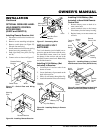
REPLACEMENT
PARTS
Note:
Use only original replacement parts.
This will protect your warranty coverage for
parts replaced under warranty.
PARTS UNDER WARRANTY
Contact authorized dealers of this product.
If they can’t supply original replacement
part(s), call DESA International’s Techni-
cal Service Department at 1-866-672-6040.
When calling DESA International, have
ready
• your name and address
• model and serial numbers of your heater
• how heater was malfunctioning
• type of gas used (propane/LP or natural
gas)
• purchase date
Usually, we will ask you to return the part to
the factory.
PARTS NOT UNDER
WARRANTY
Contact authorized dealers of this product. If
they can’t supply original replacement part(s),
call DESA International at 1-866-672-6040
for referral information. When calling DESA
International, have ready
• model number of your heater
• the replacement part number
TECHNICAL
SERVICE
You may have further questions about in-
stallation, operation, or troubleshooting.
If so, contact DESA International’s Techni-
cal Service Department at 1-866-672-6040.
You can also visit DESA International’s
technical services web site at
www.desatech.com.
SERVICE HINTS
When Gas Pressure Is Too Low
• pilot will not stay lit
• burners will have delayed ignition
• heater will not produce specified heat
You may feel your gas pressure is low. If so,
contact your local natural gas supplier.
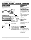
AUTO
OFF
ON
Thermopile
WIRING DIAGRAMS
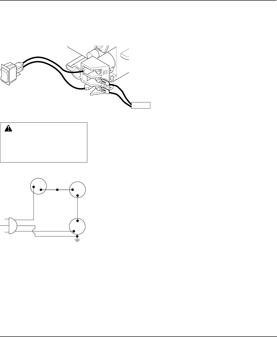
Note
: For proper operation of optional ac-
cessories, the wires from the switch to the
control must be connected exactly as shown
in Figure 39.
Figure 39 - Switch Wiring Diagram
Figure 40 - Blower Wiring Diagram
CAUTION: Label all wires prior
to disconnection when servicing
controls. Wiring errors can cause
improper and dangerous opera-
tion. Verify proper operation af-
ter servicing.