


9
105647
OWNER’S MANUAL
For more information, visit www.desatech.com
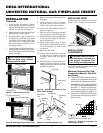
35"
17 1/4"
26 1/4"
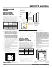
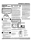
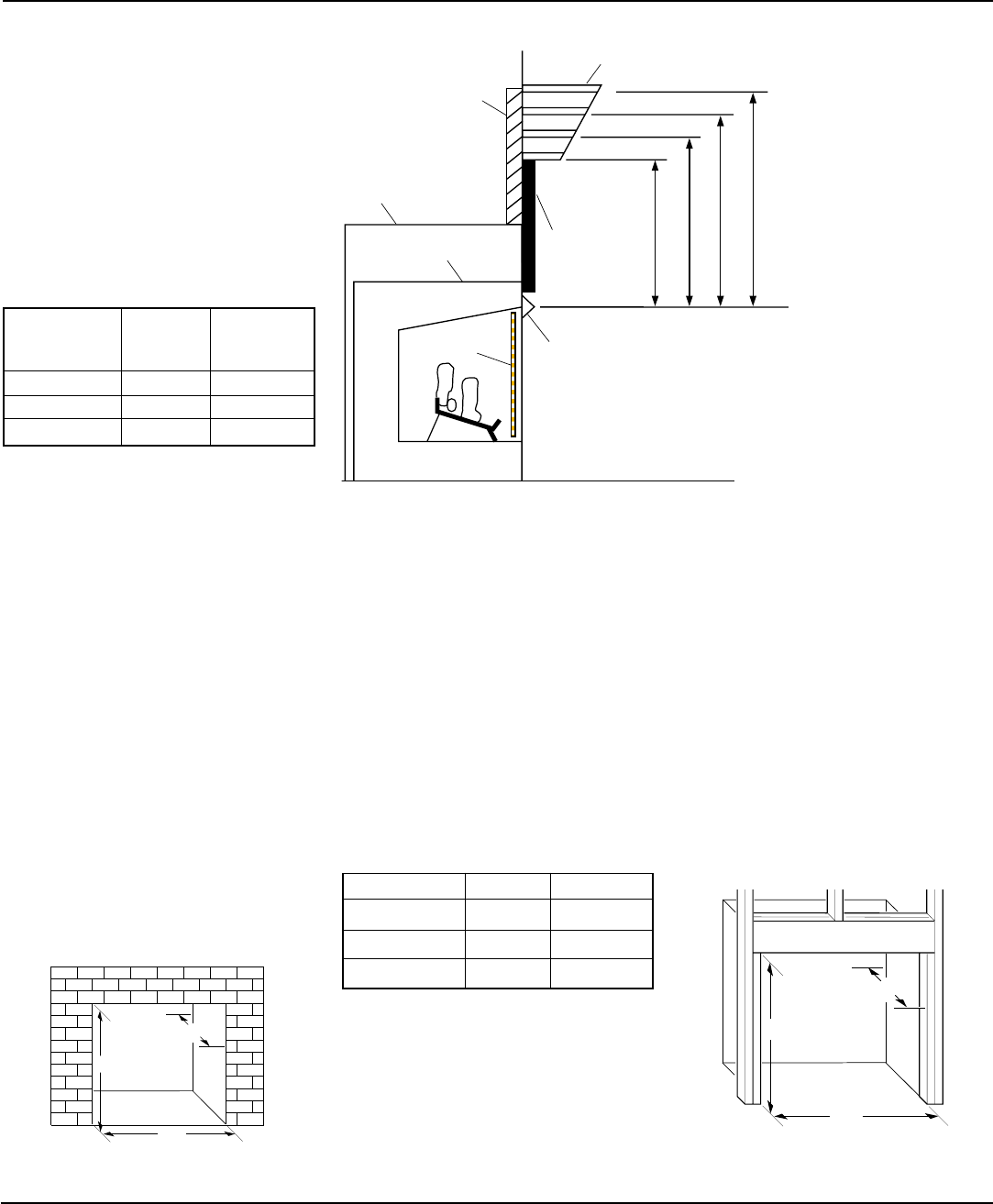
Supplied Hood Must
Be Used at All Times
Wire-mesh
Screen
Fireplace
Noncombustible
Material May
Project Off this
Surface above
the Insert Hood
Mantel Shelf
13" 16" 19" 21"
2
1
/2
"
6"
8"
10"
Fireplace Insert
Note:
All vertical
measurements are
from top of insert hood
opening to bottom
of mantel shelf.
Wall board or facing
material (above
fireplace) may be of
combustible material,
including decorative
mantel ornaments or
other similar projec-
tions off of the facing
material.
INSTALLATION
Continued
Continued
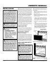
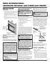
Figure 13 - Rough Opening for Installing
in Masonry Fireplace
FIREPLACE INSERT
INSTALLATION INTO
MASONRY FIREPLACE
Installation of this fireplace insert involves
installing fireplace insert into an existing ma-
sonry fireplace. If using a mantel above the
fireplace, you must follow the clearances shown
in Figure 14. Follow the instructions below to
install the fireplace insert in this manner.
1. Use dimensions shown in Figure 13 for
the masonry fireplace opening.
2. Install and properly ground GA3555,
three-prong 120 volt electrical outlet, in
fireplace insert. Follow instructions in-
cluded in kit (see Accessories, page 26).
3. Install gas piping to fireplace location. This
installation includes an approved flexible
gas line (if allowed by local codes) after
the equipment shutoff valve. The flexible
gas line must be the last item installed on
the gas piping. See Installing Gas Piping
to Fireplace Location, page 10.
4. Carefully set fireplace insert in front of
masonry fireplace with back of insert
inside wall opening.
5. Attach flexible gas line to gas supply.
See Connecting Fireplace Insert to Gas
Supply, page 10.
6. Plug electrical cord into electrical out-
let installed in step 2.
7. Carefully place fireplace insert into
masonry fireplace.
8. Check all gas connections for leaks. See
Checking Gas Connections, page 11.
9. Install brass trim after final finishing
and/or painting of wall (see Figure 11,
page 8).
Figure 14 - Minimum Mantel Clearances for Fireplace Insert Installation
Minimum
Fireplace
Insert Opening
Height 25
9
/
16
" 26
1
/
4
"
Front Width 34
5
/
16
" 35"
Depth 16
11
/
16
" 17
1
/
4
"
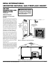
FIREPLACE INSERT
INSTALLATION INTO
FRAMED-IN ENCLOSURE
Installation of this fireplace insert involves
installing fireplace insert into a framed-in
enclosure. If using a mantel above the fire-
place, you must follow the clearances shown
in Figure 14. Follow these instructions to
install the fireplace insert in this manner.
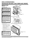
Insert Framing
Height 25
9
/
16
" 26
1
/
4
"
Front Width 34
5
/
16
" 35"
Depth 16
11
/
16
" 17
1
/
4
"
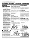
1. Frame in rough opening. Use dimen-
sions shown in Figure 15 for the rough
opening.
2. Install and properly ground GA3555,
three-prong 120 volt electrical outlet, in
fireplace insert. Follow instructions in-
cluded in kit (see Accessories, page 26).
35"
17
1
/
4
"
26
1
/
4
"
Figure 15 - Rough Opening for Installing
in Wall
3. Install gas piping into fireplace loca-
tion. This installation includes an ap-
proved flexible gas line (if allowed by
local codes) after the equipment shutoff
valve. The flexible gas line must be the
last item installed on the gas piping. See
Installing Gas Piping to Fireplace Lo-
cation, page 10.
4. Carefully set fireplace insert in front of
rough opening with back of insert in-
side wall opening.
5. Carefully set fireplace insert into rough
opening.
6. Attach flexible gas line to gas supply.
See Connecting Fireplace Insert to Gas
Supply, page 10.