


www.desatech.com
119162-01C16
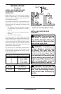
pRESSURE TESTING HEATER GAS
CONNECTIONS
1.
Open equipment shutoff valve (see Figure 15,
page 15).
2. Open main gas valve located on or near gas
meter for natural gas or open propane/LP
supply tank valve.
3. Make sure control knob of heater is in the OFF
position.
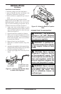
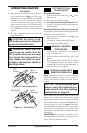
4. Check all joints from gas meter to equipment
shutoff valve for natural gas or propane/LP sup-
ply to equipment shutoff valve for propane/LP
(see Figure 16, page 16 or Figure 17). Apply
noncorrosive leak detection uid to all joints.
Bubbles forming show a leak.
5. Correct all leaks at once.
6. Light heater (see Operating Heater, page 19).
Check all other internal joints for leaks.
7.
Turn off heater (see To Turn Off Gas to Appli-
ance, page 21.
INSTALLING OpTIONAL REMOTE
ACCESSORIES
Remote control accessories are available sepa-
rately (see Accessories, page 33).
1. If unit is already installed in replace, continue
with these instructions. If unit has not been
installed in replace, go to step 6 and continue
installation of remote accessory.
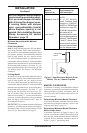
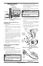
WARNING: Turn off heater
Gas Meter
Figure 17 - Checking Gas Joints (Natural
Gas Only)
Control Valve
Location
Equipment
Shutoff Valve
INSTALLATION
Continued
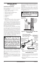
2. Carefully remove logs and set aside.
3. Locate mounting screws on sides of heater
base assembly and remove screws. Set screws
aside for reinstallation.
4. Disconnect gas line from heater base as shown
in Figure 11, page 13.
-
5. Remove heater base from replace.
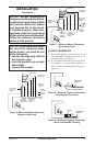
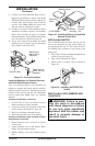
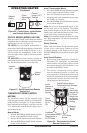
6. Install receiver bracket to base with phillips
screws provided in hardware kit as shown in
Figure 18.
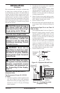
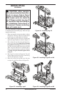
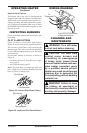
7. If installed, disconnect AUTO/OFF/ON
switch wire from control valve at TPTH and
TH locations (see Figure 19).
8. Install remote receiver into receiver bracket
using pads and push button clips provided
with receiver (see Figure 18).
Figure 18 - Installing Remote Receiver
Bracket
Figure 19 - Disconnecting Switch from
Control Valve
Remote
Receiver
Bracket
Electronic Ignitor
(On Base Assembly)
Push
Button
Clips
Pads
9-Volt
Battery
Battery
Clip
Terminal
Wires
Switch
Control
Valve