


www.desatech.com
119162-01C 17
INSTALLATION
Continued
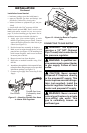
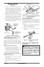
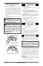
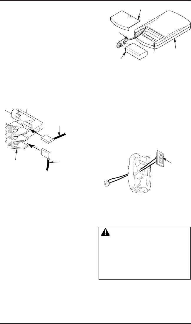
9. Connect wires from hardware pack (with re-
mote receiver bracket) to control valve at the
TPTH and TH locations as shown in Figure 20.
Connect other ends of these wires to remote
receiver wires. Note: Make sure excess wire
does not interfere with burner or pilot.
10.
If heater was removed from replace before
installation of remote accessory, see Installing
Heater Base Assembly on page 12 to reinstall
heater into replace. Test gas connection for leaks
(see Checking Gas Connections, page 15).
11. If logs were removed from heater for install
remote accessory, replace logs (see Installing
Logs, Embers and Lava Rock).
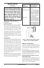
Figure 20 - Connecting Wires
Control Valve
White Wire to
White Wire on
Receiver
Red Wire to
Red Wire on
Receiver
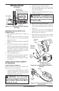
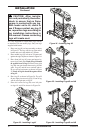
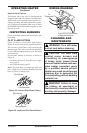
INSTALLING SWITCH
The AUTO/OFF/ON switch for this log set will
need to be installed into the small single log
accompanying this log set. This switch needs to
be installed only if remote or wall switch is not
being used.
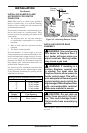
1. Slip wires of switch assembly through hole in
center of log (see Figure 22).
2. Snap switch assembly into place.
3. Attach wires to control valve as shown in
Figure 20.
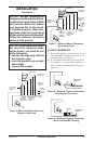
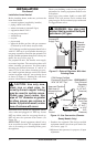
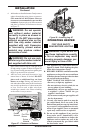
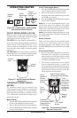
Figure 21 - Installing Battery in Hand-Held
Remote Control Unit
9-Volt Battery
Battery
Housing
Battery Cover
Terminal
Wires
Remote
Control
Unit
and Hand Held Remote Control
Two 9-volt alkaline batteries (not included) are
required to operate this heater with the wireless
hand-held remote control set. One battery must be
installed in the receiver and one in the hand-held
remote control unit. Note: Only use alkaline
batteries.
1. Locate back of receiver behind receiver
bracket mounted on base assembly.
2. Locate the battery clip mounted on the back
of the receiver (see Figure 18, page 16).
3. Slide a 9-volt battery through the clip.
4. Attach the terminal wires to the battery.
Held Remote Control Unit
1. Remove battery cover on back of remote
control unit.
2. Attach terminal wires to the battery. Place
battery into the battery housing.
3. Replace battery cover onto remote control
unit.
-
Figure 22 - Installing AUTO/OFF/ON
Switch
Switch