


www.desatech.com
119162-01C 15
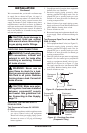
INSTALLATION
Continued
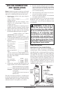
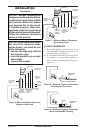
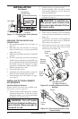
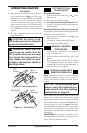
We recommend that you install a sediment trap
in supply line as shown in Figure 14, page 14.
Locate sediment trap where it is within reach for
cleaning. Install in piping system between fuel
supply and heater. Locate sediment trap where
trapped matter is not likely to freeze. A sediment
trap traps moisture and contaminants. This keeps
them from going into heater controls. If sediment
trap is not installed or is installed wrong, heater
may not run properly.
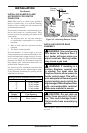
CHECKING GAS CONNECTIONS
and connections, internal and
external to unit, for leaks after
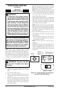
WARNING: Never use an
-
CAUTION: Make sure exter-
-
der Connecting to Gas Supply,
pRESSURE TESTING GAS SUppLY
pIpING SYSTEM
Test pressures In Excess Of 1/2 pSIG
1. Disconnect appliance with its appliance main
gas valve (control valve) and equipment
shutoff valve from gas supply piping system.
Pressures in excess of 1/2 psig will damage
heater regulator.
2. Cap off open end of gas pipe where equipment
shutoff valve was connected.
3. Pressurize supply piping system by either
opening propane/LP supply tank valve for
propane/LP gas or opening main gas valve
located on or near gas meter for natural gas
or using compressed air.
4. Check all joints of gas supply piping system.
Apply noncorrosive leak detection uid to all
joints. Bubbles forming show a leak.
5. Correct all leaks at once.
6. Reconnect heater and equipment shutoff valve
to gas supply. Check reconnected ttings for
leaks.
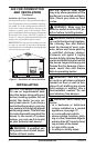
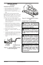
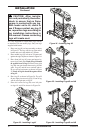
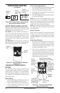
1.
Close equipment shutoff valve (see Figure 15).
2. Pressurize supply piping system by either
opening propane/LP supply tank valve for
propane/LP gas or opening main gas valve
located on or near gas meter for natural gas
or using compressed air.
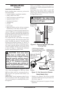
3. Check all joints from gas meter to equipment
shutoff valve for natural gas or propane/LP
supply to equipment shutoff valve for pro-
pane/LP (see Figure 16 or Figure 17, page
16). Apply noncorrosive leak detection uid
to all joints. Bubbles forming show a leak.
4. Correct all leaks at once.
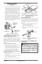
Figure 15 - Equipment Shutoff Valve
Open
Closed
Equipment
Shutoff
Valve
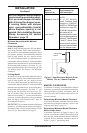
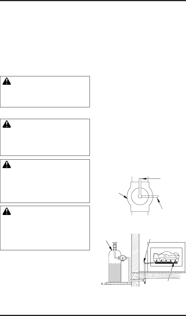
Figure 16 - Checking Gas Joints
(Propane/LP Only)
Control Valve
Location
Propane/LP
Supply Tank
Equipment
Shutoff Valve