


6
B-VENT FREESTANDING FIREPLACE
106022
SUN VALLEY STOVE COMPANY
FREESTANDING
FIREPLACE
ASSEMBLY
Continued
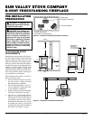
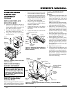
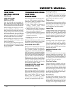
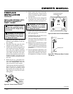
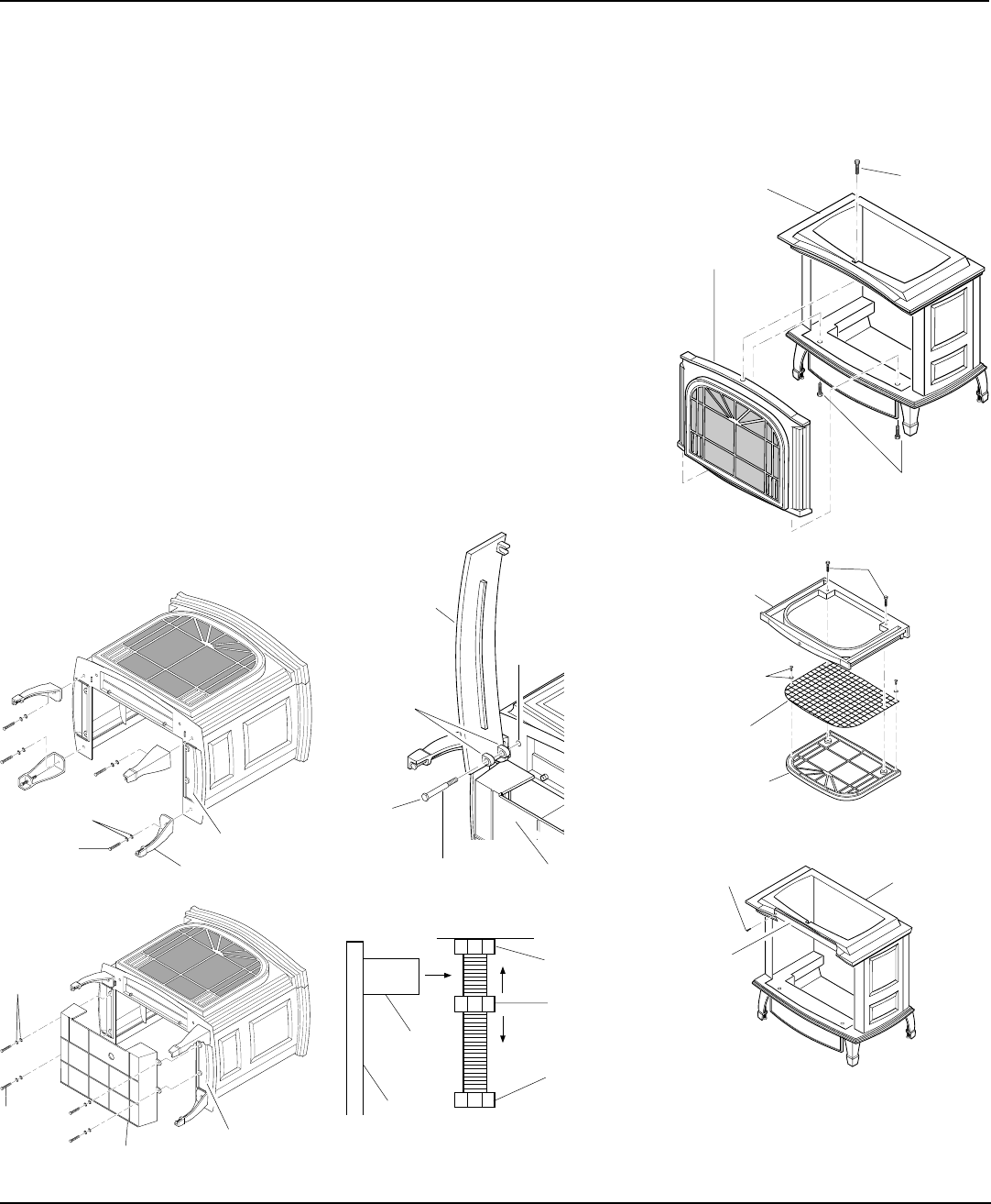
Figure 12 - Attaching Stove Door
Adjusting Nut
Bolt Stop
Catch Bolt
Door Claw
Door
Figure 13 - Catch Bolt and Door Claw
Orientation
10. Attach stove door by inserting step bolt
through door hinge pivot hole and into
threaded hole in stove body (see Fig-
ure 9, page 5 and Figure 12). Use an
adjustable wrench or a 12mm socket
to fasten step bolt. Tighten step bolt
until snug. Make sure door moves
freely.
11. Install door catch bolt (M8 x 1.25-55mm
with two M8 hex nuts) into threaded
hole on stove body (see Figure 9, page
5). Use an adjustable wrench or a 12mm
socket. The catch bolt has two hex nuts
attached to it (see Figure 13). The top
nut is a bolt stop and the bottom nut is
for door leveling adjustment.
12. Check general catch bolt alignment
with door claw. Make final adjustment
and door leveling after stove is in nor-
mal standing position.
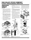
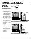
Figure 10 - Attaching Stove Legs
Bottom Of
Stove Unit
Leg
Bolt
Washers
Figure 11 - Attaching Stove Bottom
Bottom Of
Stove Unit
Bolt
Washers
Stove Bottom
Step
Bolt
Door
Hinge
Threaded
Hole
Stove
Door
Stove
Bottom
Bolt
Shoulder
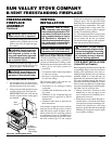
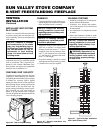
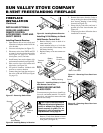
13. Carefully lift stove back up on its four
attached legs.
14. Remove 2 bolts from bottom of stove
and one from the top of the stove to
remove the front panel assembly (see
Figure 14).
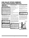
15. Lay the front panel assembly face down
on a protected surface. Remove the two
screws that hold the front plate onto the
front surround plate (see Figure 15).
Save these screws.
16. Remove the seven screws and washers
that hold the screen onto the front sur-
round plate. Discard these screws,
washers, and screen. They are for vent-
free use only (see Figure 15).
17. Replace the two screws from step 15
to reassemble the front plate and the
front surround plate. Set this assembly
aside until stove heater has been in-
stalled, logs have been placed inside of
heater, and glass door to heater insert
has been replaced.
18. Remove the two screws that secure the
metal plate located across the front sec-
tion at the top of the stove body (see Fig-
ure 16). Discard these screws and metal
plate. They are for vent-free use only.
19. Set three top grate sections into stove top.
Figure 14 - Removing Front Assembly
Front
Assembly
Bolt
Bolts
Stove
Body
Figure 15 - Removing Screen from Front
Assembly
Figure 16 - Removing Metal Plate from
Stove Body
Screw
Metal
Plate
Stove
Body
Screws
Front
Surround
Plate
Front Plate
Screen
Screw with
Washer