


9
106022
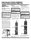
OWNER’S MANUAL
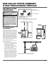
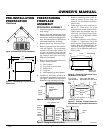
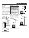
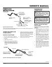
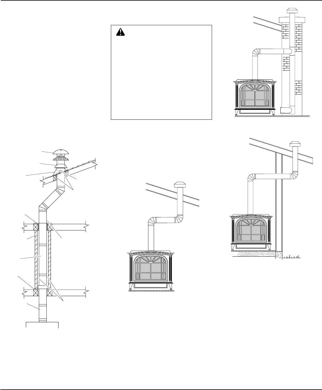
Figure 21 - Typical B-Vent Installation
WARNING: Installation should
only be made by qualified per-
sons who are familiar with the
safety procedures required for
the installation of the product,
who are equipped with the proper
tools and testing instruments,
and who have achieved proper
certification of licensing. Instal-
lations made by unqualified per-
sons can result in the risk of in-
jury or electrical shock which can
be serious or even fatal.
INSTALLATION OF LISTED
B-1 VENT
VENTING
INSTALLATION
Continued
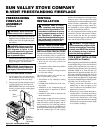
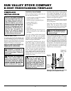
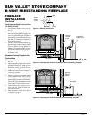
Figures 22, 23 and 24 show other options
for the gas vent. When venting through a
side wall your vent pipe must have the
proper temperature rating (see Figure 24).
Manufacturer’s clearances must also be
maintained. Consult the authority having
jurisdiction in your area regarding venting
through side wall.
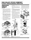
Figure 22 - Vertical Venting Through
Ceiling Using Two 90
°
Elbows
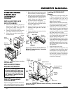
Figure 23 - Vertical Venting Configuration
Through Chimney
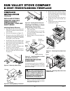
Figure 24 - Venting Through a Side Wall
Continued
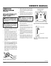
Round Top
Storm Collar
Flashing
Roof
Support
25mm (1")
Clearance to
Combustible
Material
Firestop
Spacer
Keep Electrical
Wires and Building
Insulation Away
from Gas Vent and
Out of the Required
Air Space
Enclosure
Wall
Gas Vent
Length
25mm (1")
Clearance to
Combustibles
Support
Plate
Adjustable
Length
• Situate the gas vent in the structure so
that it can be installed without cutting
joists, sills, plates, or major load bearing
partitions or members. It is also impor-
tant to locate the base of the gas vent as
near as possible to the heating appliance.
• This heater must be properly connected to
a venting system. This heater is equipped
with a vent safety shutoff system.
• Use only vents labeled "FOR EXTE-
RIOR USE" above the roofline.
• Consult the authority having jurisdiction to
select the correct gas vent diameter. Avoid
using a larger than necessary diameter.