


www.desatech.com
119505-01E8
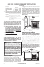
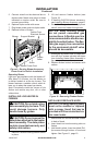
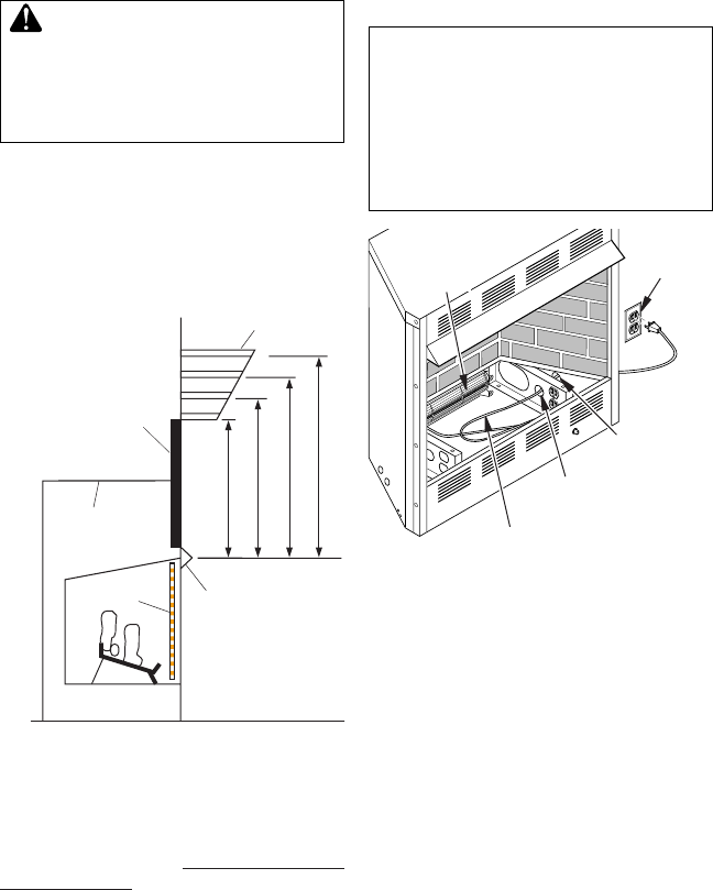
Supplied
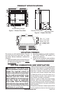
Firebox Hood
Must Be Used
at All Times
Wire-mesh
Screen
Firebox
Mantel Shelf
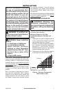
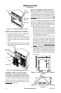
13" 16" 19" 21"
2
1
/2
"
6"
8"
10"
For
CGFB32C
Series
circulating
louvered
models
only
Note:
A
ll vertical measurements
are from top of fireplace
opening to bottom of mantel
shelf. All measurements
are in inches.
Facing material (above
firebox) may be of
combustible material,
including decorative
mantel ornaments.
Mantel Clearances for Built-In
Installation
If placing custom mantel above built-in re-
box, you must meet the minimum allowable
clearance between mantel shelf and top of
rebox opening shown in Figure 7. These are
the minimum allowable mantel clearances
for a safe installation. Use larger clearances
wherever possible to minimize the heating of
objects and materials placed on the mantel.
CAUTION: Close screens
If your installation does not meet the minimum
clearances in Figure 7, you must:
• raise mantel to an acceptable height,
OR
• remove mantel.
INSTALLATION
Continued
Figure 7 - Minimum Mantel Clearances
for Built-In Installation
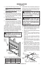
INSTALLING BLOWER ACCESSORY
You may install blower accessory GA3750A
with conventional installation (below) or with
built-in installation (see Built-In Installation of
Blower Accessory). To install blower accessory,
see instruction sheet included with the kit.
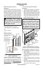
Side
Opening
Support Bracket
Opening
Blower Power
Cord
Figure 8 - Routing Blower Accessory
Power Cord for Conventional Installation
Electrical
Outlet
Blower
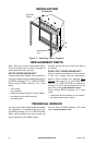
Built-In Installation of Blower Accessory
1. Install blower assembly per instruction
sheet included.
2. Before replacing bottom of rebox, re-
move screw holding duplex outlet to sup-
port bracket in bottom of rebox. Remove
duplex outlet.
3. Clamp electrical cable into firebox
through smallest hole using strain relief
provided.
4. Route wires from electrical box through
hole in side of heater and hole in support
bracket (see Figure 9, page 9).
Conventional Installation of Blower
Accessory
1. Install blower assembly per instruction
sheet included in blower accessory kit.
2. Before replacing bottom of rebox, route
blower power cord through hole in support
bracket in bottom of rebox and through
hole in side of rebox to grounded, three-
prong 120 volt electrical outlet (see Fig-
ure 8). Plug electrical cord into outlet.
3. Replace bottom of rebox.
-
the National Electrical Code,
ANSI/NFPA 70 (Latest Edition)