


www.desatech.com
119505-01E 11
INSTALLATION
Continued
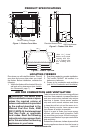
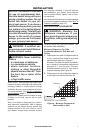
Actual
Height
32
1
/
2
" 33"
Front Width
34
5
/
16
" 34
3
/
4
"
Depth
16
11
/
16
" 17
3
/
4
"
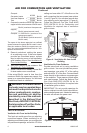
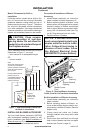
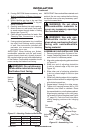
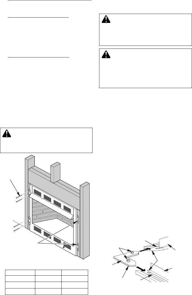
Figure 15 - Attaching Firebox to Wall Studs
Nailing
Flanges
Nails or
Wood
Screws
4. If using GA3750A blower accessory, see
Built-In Installation of Blower Accessory,
page 8.
5. Attach exible gas line to log set. See
Connecting to Gas Supply in log set
owner’s manual.
6.
Carefully insert rebox into rough opening.
7. Attach rebox to wall studs using nails
or wood screws through holes in nailing
ange (see Figure 15).
8. Check all gas connections for leaks. See
Checking Gas Connections in log set
owner’s manual.
9. If using optional perimeter trim, install the
trim after nal nishing and/or painting
of wall. See instructions included with
perimeter trim accessory for attaching
perimeter trim or see.
IMPORTANT: When nishing your rebox,
combustible materials such as wall board,
gypsum board, sheet rock, drywall, plywood,
etc. may be butted up next to the sides and top
of the rebox. Combustible materials should
never overlap the rebox front facing.
WARNING: Do not allow any
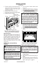
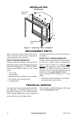
Figure 16 - Assembling Trim
Top Trim
Mitered Edge
Side Trim
Slot
Shim
Adjusting
Plate
Set
Screws
Slot
IMPORTANT: Noncombustible materials such
as brick, tile, etc. may overlap the front facing,
but should never cover any necessary open-
ings like louvered slots.
WARNING: Do not allow
WARNING: Use only non-
-
ASSEMBLING AND INSTALLING TRIM
1. Remove packaging from 3 pieces of trim.
2. Locate 2 adjusting plates with set screws
and 2 shims in hardware packet.
3. Align shim under adjusting plate as shown
in Figure 16.
4. Slide one end of adjusting plate/shim
in slot on mitered edge of top trim (see
Figure 16).
5. Slide other end of adjusting plate/shim
in slot on mitered edge of side trim (see
Figure 16).
6. While rmly holding edges of trim together,
tighten both set screws on adjusting plate
with slotted screwdriver.
7. Repeat steps 2 through 6 or other corner.
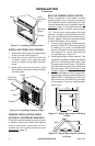
8. Tighten trim hanging screws (#10 x 6.25
shoulder) into holes in cabinets. Place
the assembled trim onto replace cabinet.
Align hanging notches on trim with hang-
ing screws on side of replace (see Figure
17, page 12). Push trim rmly into place,
sliding hanging notches over hanging
screws.