


www.desatech.com
111044-01J14
INSTALLATION
Continued
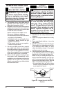
For Built-In Installation
WARNING: A licensed elec-
-
Follow instructions in Removing Valve Cover
Shield, page 12, then
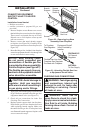
1. Install a snap bushing found in hardware kit
into one of the holes found on rear of valve
cover shield. The other hole is for a strain
relief clamp (not supplied) to secure incoming
electrical supply.
2. Follow steps 2 through 6 in Installing Blower
Assembly, page 12. Also remove black wire
from middle switch terminal 2.
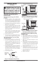
3.
Remove black plastic strain relief and power
cord from switch plate. The power cord supplied
will not be used in built-in installations. Pop in
the plastic snap bushing found in hardware kit
into the hole left by supply cord/strain relief.
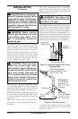
4. A licensed electrician must follow the wiring
diagram to connect incoming electrical supply
to fan kit wiring harness (see Figure 16).
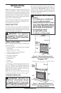
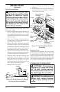
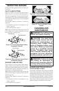
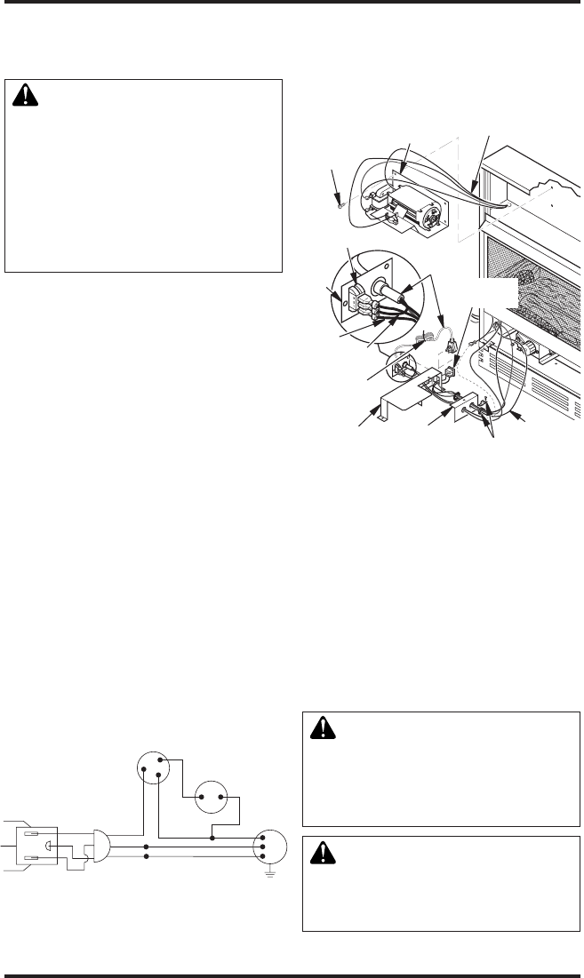
5. Plug power cord to the outlet receptacle (not
provided) as shown in Figure 17. Wind the
extra cable in power cord and tie it up with
the plastic wire strap (see Figure 17). Set the
cable bundle between the burner bracket and
outer casing, away from the burner.
6. Reinstall valve cover shield.
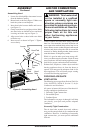
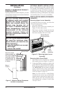
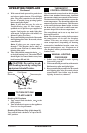
Figure 16 - Wiring Diagram For Blower
Accessory Built-In Installation
Red
Red
Fan Switch
(Auto/Off/On)
Blue
Blue
Thermostat
Switch
(N.O.)
Green
White
Green
White
On
110/115
V.A.C.
Blower
Motor
Black
Off
1
2
3
Auto
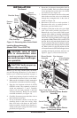
Blower Bracket
Assembly
Screw
Wire
Harness
Power
Cord
Valve Cover
Shield
Box
Cover
Wire
Harness
Switch
Plate
Switch
Clamp
Connector
(not included)
Outlet
Receptacle
Blue
Red
Plastic Wire
Strap
Figure 17 - Installing Blower Bracket
Assembly
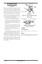
Extension Cord
Use extension cord if needed. The cord must have
a three-prong, grounding plug and a three-hole
receptacle. Make sure cord is in good shape. It must
be heavy enough to carry the current needed. An un-
dersized cord will cause a drop in line voltage. This
will result in loss of power and overheating. Use a
No. 16 AWG cord for lengths less than 50 feet.
7. Test to make sure the blower is working
properly.
8. Reinstall upper louver assembly and hood if
previously removed, (see Figure 13, page 12).
Close lower louver door.