


www.desatech.com
111044-01J10
-
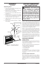
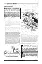
currents move heat to wall sur-
smoke, aromatic candles, clean-
IMPORTANT: Vent-free replaces add moisture
to the air. Although this is benecial, installing re-
place in rooms without enough ventilation air may
cause mildew to form from too much moisture. See
Air for Combustion and Ventilation, page 6.
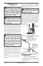
Note: When installing replace directly on carpet-
ing, tile or other combustible material, other than
wood ooring, the replace shall be installed on a
metal or wood panel extending the full width and
depth of the replace.
CAUTION: If you install the
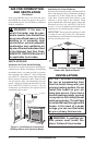
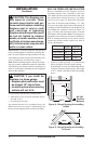
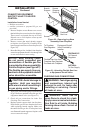
For convenience and efciency, install replace
• where there is easy access for operation, inspec-
tion and service.
• in coldest part of room
An optional blower kit is available from your
dealer. See Accessories, page 27. If planning to use
blower, locate replace near an electrical outlet.
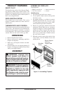
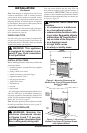
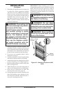
Built-in installation of this fireplace involves
installing replace into a framed-in enclosure.
This makes the front of replace ush with wall.
An optional brass trim kit accessory is available
(see Accessories, page 27). Brass trim will extend
past sides of replace approximately 1/2". This
will cover the rough edges of the wall opening. If
installing a built-in mantel above the replace, you
must follow the clearances shown in Figure 12,
page 12. Follow the instructions below to install
the replace in this manner. Note: Your replace is
designed to be used in zero clearance installations.
Wall or framing material can be placed directly
against any exterior surface on the rear, sides or
top of your replace.
Actual Framing
Height 26" 26
7
/
8
"
Front Width 26
3
/
4
" 26
7
/
8
"
Depth 9
1
/
2
" 10
1
/
2
"
Bottom 3/4" 3/4"
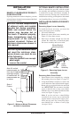
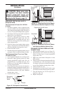
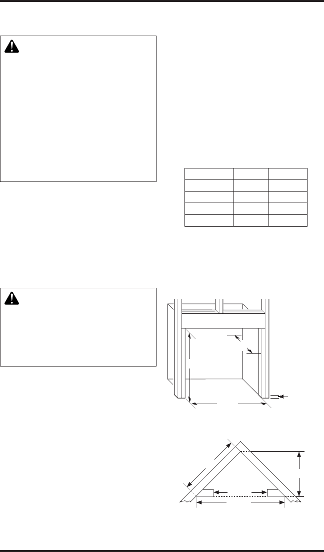
1. Frame in rough opening. Use dimensions
shown in Figure 8 for the rough opening.
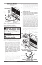
If installing in a corner, use dimensions shown
in Figure 9 for the rough opening. The height
is 26
7
/
8
" which is the same as the wall opening
above.
36
5
/
8
"
25
7
/
8
"
51
3
/
4
"
26
7
/
8
"
26
7
/
8
"
26
7
/
8
"
3/4" Off
The Floo
r
Minimum
10
1
/
2
"
Figure 8 - Rough Opening for Installing
in Wall
Figure 9 - Rough Opening for Installing
in Corner
INSTALLATION
Continued