


www.desatech.com
111044-01J12
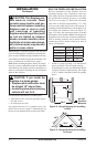
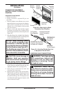
13"
16"
19"
21"
2
1
/2"
6"
8"
10"
Note:
A
ll vertical
measurements
are from top of
fireplace
opening to
bottom of
mantel shelf. All
measurements
are in inches.
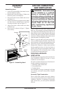
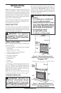
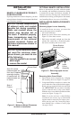
MANTEL CLEARANCES FOR BUILT-
IN INSTALLATION
If placing mantel above built-in replace, you must
meet minimum clearance between mantel shelf and
top of replace opening.
minimum clearances shown in
NOTICE: If your installation does
not meet the minimum clear-
ances shown, you must do one
-
• remove the mantel
INSTALLATION
Continued
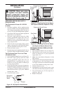
Figure 11 - Minimum Mantel Clearances
for Built-In Installation
Mantel Shelf
Note: All vertical
measurements are
from top of replace
opening to bottom
of mantel shelf. All
measurements are
in inches.
Side of
Firebox
Refer to instructions provided with the mantel
for assembly and installation instructions. Refer
to instructions on page 4 for rebox assembly. If
a blower accessory is being used, it should be in-
stalled before securing your replace to the mantel
(see Installing Blower Accessory GA3450TA).
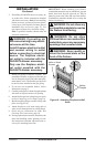
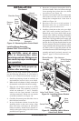
INSTALLING BLOWER ACCESSORY
GA3450TA
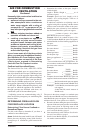
To install the blower accessory, you must rst
remove the upper louver assembly.
1. Lift screen off heater.
2. Remove 4 screws from louver assembly (see
Figure 12). Save these screws.
3. Pull louver assembly straight out from the
cabinet. Be careful not to scratch the paint.
Set louver assembly and screws aside.
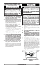
Figure 12 - Removing Upper Louver
Assembly
Upper
Louver
Assembly
Screws
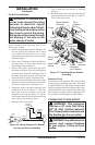
Blower Bracket
Mounting Holes
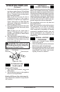
1. Open bottom louver assembly by swinging
the assembly down (see Figure 13, page 13).
2. Using short Phillips screwdriver, remove the
screw under the center of the branch support.
Rotate valve cover shield clockwise and slide
out. IMPORTANT: Do not remove shoulder
screw on the left side of valve cover shield.
Slide the valve cover shield off of the shoulder
screw (see Figure 13, page 13).
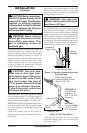
Note: If you do not have a short Phillips
screwdriver, the screen, log set and branch
support must be removed so a longer screw-
driver may be used. See Connecting Equip-
ment Shutoff Valve to Heater Control, page
16, steps 1 and 2.