


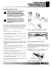

ELECTRIC FIREPLACE
INSTALLATION INSTRUCTIONS
Models: (V)E32L, (V)E32LB, (V)E32LH, (V)E32LBH
(V)E36L, (V)E36LB, (V)E36LH and (V)E36LBH
OPTIONAL HEATER ACCESSORY Continued
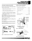
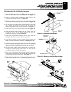
1. Open the upper control door (see Figure 11, on page 6) and
remove the 2 Phillips screws below heater grill. See Figure 19.
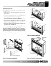
2. Remove 2 Phillips screws holding the control cover to the
control panel inside the firebox (see Figure 20).
3. Slide the control cover to the right and swing out the locking
tabs from the notched openings on top. See detail on Figure 20.
4. Let the control cover hang down off the harnesses. Be careful
not to damage any wiring. If necessary you can unscrew the
harness strap at the blower mount to gain slack. See Figure 21.
5. Remove the 2 Hex screws at rear blower mount. See Figure 20.
6. Slide the blower mount towards the rear firebox until the
locking tabs line up with the notched openings and lower the
mount down and away. See detail Figure 20.
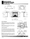
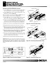
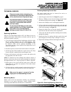
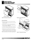
7. Remove the blower/heater assembly with 4 screws from the
packaging. The blower is pre-wired for convenience.
8. Align blower assembly over hole pattern on blower mount and
attach with 4 pan head screws provided. See Figures 21 or 22.
9. With the discharge pointing towards you, guide the assembled
blower mount into the firebox and center the rear mounting
flanges between the standoff brackets against the rear firebox.
10. Lift the blower mount up and position the 4 locking tabs
through the notched openings in the firebox top, then slide the
assembly forward until locked into position.
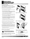
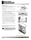
11. Remove the control panel knockout plug located in the heater
switch position by depressing the locking tabs and pushing the
plug out through the front of the panel. See Figure 23.
12. Firmly insert the red power switch, provided, into the open
mount location with the “ON” ( I ) indicator positioned on top.
9
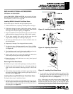
MOUNTING
SCREWS
BLOWER MOUNT
HEATER/BLOWER.
ASSEMBLY
HARNESS
STRAP
Figure 21 - Mounting Heater/Blower
F
F
o
o
r
r
m
m
o
o
r
r
e
e
i
i
n
n
f
f
o
o
r
r
m
m
a
a
t
t
i
i
o
o
n
n
,
,
v
v
i
i
s
s
i
i
t
t
w
w
w
w
w
w
.
.
d
d
e
e
s
s
a
a
t
t
e
e
c
c
h
h
.
.
c
c
o
o
m
m
111076-01C
MOUNTING
SCREWS
BLOWER MOUNT
HEATER/BLOWER.
ASSEMBLY
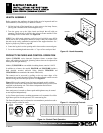
Figure 22 – Mounting Alternate Blower/Heater
BLOWER MOUNT
CONTROL COVER
PANEL
SCREWS
TAB RELEASE
Figure 20 – Disassembling Blower Mount
KNOCKOUT PLUG
POWER
MOUNT LOCATION
MOUNT LOCATION
CONTROL PANEL
CONTROL PANEL
SWITCH
Figure 23 - Installing Heater Power Switch