


ELECTRIC FIREPLACE
INSTALLATION INSTRUCTIONS
Models: (V)E32L, (V)E32LB, (V)E32LH, (V)E32LBH
(V)E36L, (V)E36LB, (V)E36LH and (V)E36LBH
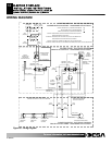
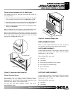
Accessing Imaging Unit
The imaging unit can be accessed from inside the firebox for
servicing as follows:
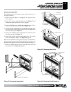
1. Remove the glass doors (if equipped). See Optional Glass
Doors, page 7.
2. Remove the screens, grate and brick liners. See Figure 32 and
instructions under Optional Brick Liners, page 8).
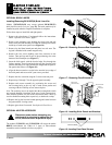
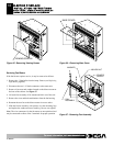
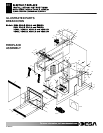
3. Remove 4 Phillips screws holding the hearth pan to the firebox
and 2 located at the lower frame rail (see Figure 33).
4. Lift the rear ends of the hearth pan up until the front edge clears
the lower frame rail then slide up on one end and angle out of
the firebox opening. See Figure 33.
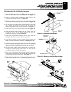
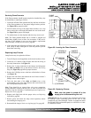
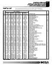
5. Remove the 4 Phillips screws holding the face extensions at the
top refractory clips. See Figure 34.
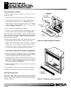
6. Remove the viewing screen from the cabinet face. The viewing
screen is attached by magnets. See Figure 35, page 16.
Note: Do not scratch the viewing screen. Place it on a nonabrasive
surface away from work area. When replacing the viewing screen
the painted side must face inside of cabinet with pattern facing up.
7. Remove 4 Phillips screws on base cover and lift the cover off
the cabinet base. See Figure 36, page 16.
15
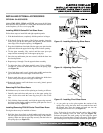
REFRACTORY BRACKET
Figure 32 - Accessing Imaging Unit
F
F
o
o
r
r
m
m
o
o
r
r
e
e
i
i
n
n
f
f
o
o
r
r
m
m
a
a
t
t
i
i
o
o
n
n
,
,
v
v
i
i
s
s
i
i
t
t
w
w
w
w
w
w
.
.
d
d
e
e
s
s
a
a
t
t
e
e
c
c
h
h
.
.
c
c
o
o
m
m
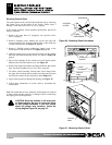
LOWER RAIL
2 SCREWS @
4 SCREWS @
HEARTH PANEL
HEARTH PANEL
Figure 33 - Removing Hearth Pan
111076-01C
FACE
REFRACTORY
CLIP
EXTENSION
Figure 34 - Removing Face Extensions