


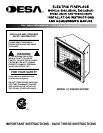
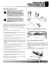

ELECTRIC FIREPLACE
INSTALLATION INSTRUCTIONS
Models: (V)E32L, (V)E32LB, (V)E32LH, (V)E32LBH
V)E36L, (V)E36LB, (V)E36LH and (V)E36LBH
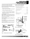
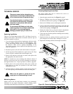
LOCATING THE FIREPLACE HEATER
Plan where to locate and frame the fireplace heater. This will
save time and money later when you install the fireplace. Before
installation consider the following:
1. Where the firebox is located must allow for wall and ceiling
clearances (see Installation Clearances).
2. Consider a location where the appliance screen will not be
exposed to direct sunlight from windows or doors.
3. A 15 ampere, 120 Volt, 60 Hz branch circuit with proper
ground must be available at the location. Preferably a
dedicated branch circuit should be provided to avoid circuit
breakers to trip or fuses to blow.
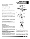
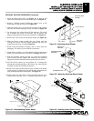
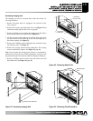
Flush installations are recommended where living space is
limited or at a premium. Since the space required to enclose the
appliance would be located beyond an outside wall, this
installation would require additional planning and construction.
Check local codes for any restrictions.
Projected installations can extend any distance into the
room. A projection may be ideal for a new addition on an
existing, finished wall.
Corner installations make use of space that may not normally
be used and provides wider and more efficient heat distribution.
Internal wall installations provide a discreet option for room
separation and can also be an ideal addition to an existing wall.
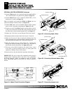
INSTALLATION CLEARANCES
Minimum clearances to combustible are:
• Top, Back and Sides of Recessed Cabinet ……… 0” Min.
• Drywall to Sides of Front Face …………………. 0” Min.
• Framing at Nailing Flanges ...…………………… 0” Min.
• Ceiling to Opening ……………………………… 36” Min.
• Floor ………………………………………………. 0” Min.
• Front …………………………………………….. 36” Min.
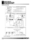
• Perpendicular Side Wall …………………………10” Min.
• Mantle Clearances …………………….. See Figures 2 and 3
3
F
F
o
o
r
r
m
m
o
o
r
r
e
e
i
i
n
n
f
f
o
o
r
r
m
m
a
a
t
t
i
i
o
o
n
n
,
,
v
v
i
i
s
s
i
i
t
t
w
w
w
w
w
w
.
.
d
d
e
e
s
s
a
a
t
t
e
e
c
c
h
h
.
.
c
c
o
o
m
m
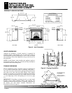
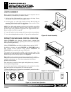
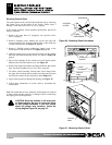
12"
10 1/2" MIN.
REF.
16 5/8"
OF CABINET
TOP
FACING MATERIAL MAY
BE NON-CUMBUSTIBLE
REF.
MANTELS AND TRIMS
COMBUSTIBLE WOOD
9 5/8" REF.
NOTE: ALL MANTEL CLEARANCES
ARE MEASURED FROM TOP
FRAMING
OF FIREPLACE OPENING
MAY EXTEND ABOVE
THE PROFILE SHOWN
WALL TREATMENTS OR
COMBUSTIBLE WOOD.
MATERIAL
WHEN MAINTAINED
WITHIN THE 30 DEGREE
PARAMETER SHOWN
Figure 2 – Mantel Clearances
Figure 1 - Possible Locations for Installation
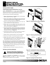
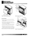
EDGE OF FIREBOX
1 3/4" MAX.
3"
MINIMUM 10" FROM
PERPENDICULAR SIDE WALL
OPENING
30°
TOP VIEW OF FIREPLACE
5"
SAFE ZONE
MUST NOT OVERLAP
COMBUSTIBLE MATERIAL
FRONT FACE
Figure 3 - Mantel Side Clearance
111076-01C