


ELECTRIC FIREPLACE
INSTALLATION INSTRUCTIONS
Models: (V)E32L, (V)E32LB, (V)E32LH, (V)E32LBH
(V)E36L, (V)E36LB, (V)E36LH and (V)E36LBH
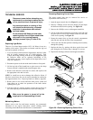
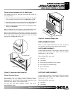
Further Accessing Imaging Unit For Replacement
The imaging unit can be removed from inside the firebox for
servicing as follows:
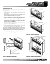
1. Remove 4 Hex screws on the lower louver panel and detach the
louver assembly from the front face. See Figure 41, page 18.
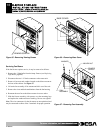
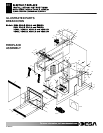
2. Rotate the top edge of lower frame rail inward and lift upward
until locking tabs detach from the front face (see Figure 42).
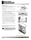
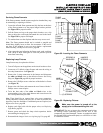
3. Slide the entire imaging forward and lift out through the front
opening (see Figure 43).
Note: An additional 3 feet of harness is tucked behind the imager
to permit removal without disconnecting any control wiring.
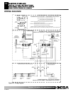
Note: If full replacement of the imager is necessary, the wiring
harnesses must be disconnected and the new harnesses reconnected
at the control panel. For proper connection, follow the wiring
diagram show in Figure 28, on page 12.
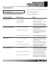
Further Technical Service
You may have further questions about installation, operation or
troubleshooting. If so, contact DESA Technical Service
Department at 1-866-672-6040. When calling, please have your
model and serial numbers of your fireplace ready.
You can also visit DESA technical service’s web site at
www.desatech.com.
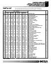
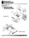
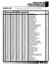
REPLACEMENT PARTS
Note: Use only original replacement parts. This will protect
your warranty coverage for parts replaced under warranty.
PARTS UNDER WARRANTY
Contact authorized dealers of this product. If they can’t supply
original replacement part(s), call DESA Technical Service
Department at 1-866-672-6040.
When calling DESA, have ready:
● your name
● your address
● model and serial numbers of your fireplace
● how fireplace was malfunctioning
● type of accessories
● purchase date
PARTS NOT UNDER WARRANTY
Contact authorized dealers of this product. If they can’t supply
original replacement part(s), call DESA Technical Service
Department at 1-866-672-6040.
When calling DESA, have ready:
● your name
● your address
F
F
o
o
r
r
m
m
o
o
r
r
e
e
i
i
n
n
f
f
o
o
r
r
m
m
a
a
t
t
i
i
o
o
n
n
,
,
v
v
i
i
s
s
i
i
t
t
w
w
w
w
w
w
.
.
d
d
e
e
s
s
a
a
t
t
e
e
c
c
h
h
.
.
c
c
o
o
m
m
111076-01C
19
UPPER RAIL
LOCKING TAB
Figure 42 - Removing Lower Frame Rail
IMAGING UNIT
Figure 43 - Removing Imaging Unit