


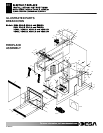

ELECTRIC FIREPLACE
INSTALLATION INSTRUCTIONS
Models: (V)E32L, (V)E32LB, (V)E32LH, (V)E32LBH
(V)E36L, (V)E36LB, (V)E36LH and (V)E36LBH
Servicing Flame Pennants
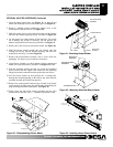
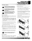
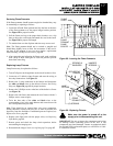
If the flame pennants should become tangled or detached they may
be reattaching or replacing as follows:
1. Locate the affected flame pennant and slip the hem at the base
of the flame pennant over the proper hanger bracket position.
See Figure 38 for proper location.
2. Pull the flame cord up to the proper hook location, use a slip
knot to adjust the cord length and attach the cord to the hook.
See Figure 38 for proper cord length.
3. Tie another knot over the slip knot and trim away access cord.
Note: The flame pennant should not be twisted or tangled and
should hang slightly loose to allow free movement. If the cord is
too short or the pennant is torn you must obtain a replacement
flame assembly, See Replacement Parts, page 19.
4. After connecting and adjusting the flame cords, soak each knot
with a drop of white wood glue or clear nail polish to prevent
them from unraveling.
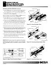
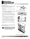
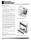
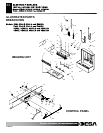
Replacing Lamp Fixtures
Lamp fixtures may be replaced as follows:
1. Turn off all power to the appliance at the circuit breaker or fuse.
2. Locate any of 3 defective lamp fixtures and trace the wiring to
the crimp connections. See Figure 39.
3. Remove the 2 crimp connectors in the harness and disconnect
the white and black wires on the defective fixture. See Wiring
Diagram, Figure 28, page 12 for proper locations.
4. Remove the 2 Phillips screws at the base of the defective fixture
(see Figure 39).
5. Remove the old fixture and remount the new fixture with the 2
Phillips screws removed prior.
6. Twist the bare ends of the white and black wires to the
corresponding wires in the main harness and secure them with
the 2 crimp connectors provided.
Note: There should be no exposed bare wire at any connection.
Wiring should be secured with wire ties, as short as possible and
kept away from the fan blades. If additional parts are required, see
Replacement Parts, page 19.
6. Replace each light bulb with the proper color, see Replacing
Light Bulbs, page 13.
7. Restore power and check the lamp circuit operation, before
reassembling the imaging unit.
8. Reassemble the imager. See Accessing Imaging Unit, page 15.
IMPORTANT: Be sure to inspect the components and wiring
for damage before connecting power to the unit. If any
components are found damaged, contact an authorized dealer
for original DESA replacement part(s) or call DESA at 1-866-
872-6040 for referral.
3 1/2"
CORD
FLAME
PENNANT
FLAME
8"
7"
1 1/2"
SPACER
FLAME
Figure 38 - Locating the Flame Pennants
17
RIBBON
REFLECTIVE
HANGER
SCREWS
LAMP
FIXTURE
(2) SCREWS
CRIMP
CONNECTORS
SCREWS &
WASHERS
Figure 39 - Replacing Fixtures
Make sure the power is turned off at the
supply prior to disassembling this unit.
F
F
o
o
r
r
m
m
o
o
r
r
e
e
i
i
n
n
f
f
o
o
r
r
m
m
a
a
t
t
i
i
o
o
n
n
,
,
v
v
i
i
s
s
i
i
t
t
w
w
w
w
w
w
.
.
d
d
e
e
s
s
a
a
t
t
e
e
c
c
h
h
.
.
c
c
o
o
m
m
111076-01C