


111739-01A
For more information, visit www.desatech.com
For more information, visit www.desatech.com
8
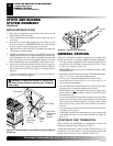
7. Remove original pilot orifice using needlenose pliers or fin-
gertips. Replace with the pilot orifice supplied with conversion
kit.
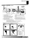
Note:
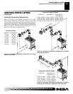
The new pilot orifice has 014 LP stamped on it for
identification purposes (see Figure 15).
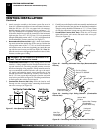
8. Place open end of conversion pilot orifice into pilot barrel (see
Figure 14).
IMPORTANT:
Make sure the pilot orifice is properly mated
and aligned inside pilot barrel.
9. Replace pilot target removed in step 5. Tighten pilot target hex
fitting until the pilot target aligns with the thermocouple and
thermopile (see Figure 16, page 9).
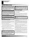
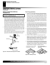
10. Replace original burner with burner supplied with conversion
kit. The new burner for propane gas will have four (4) primary
air holes near the burner inlet (see Figure 12). Attach with the
two 5/16" hex mounting screws removed in step 4.
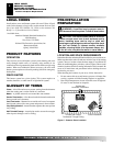
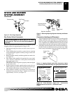
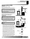
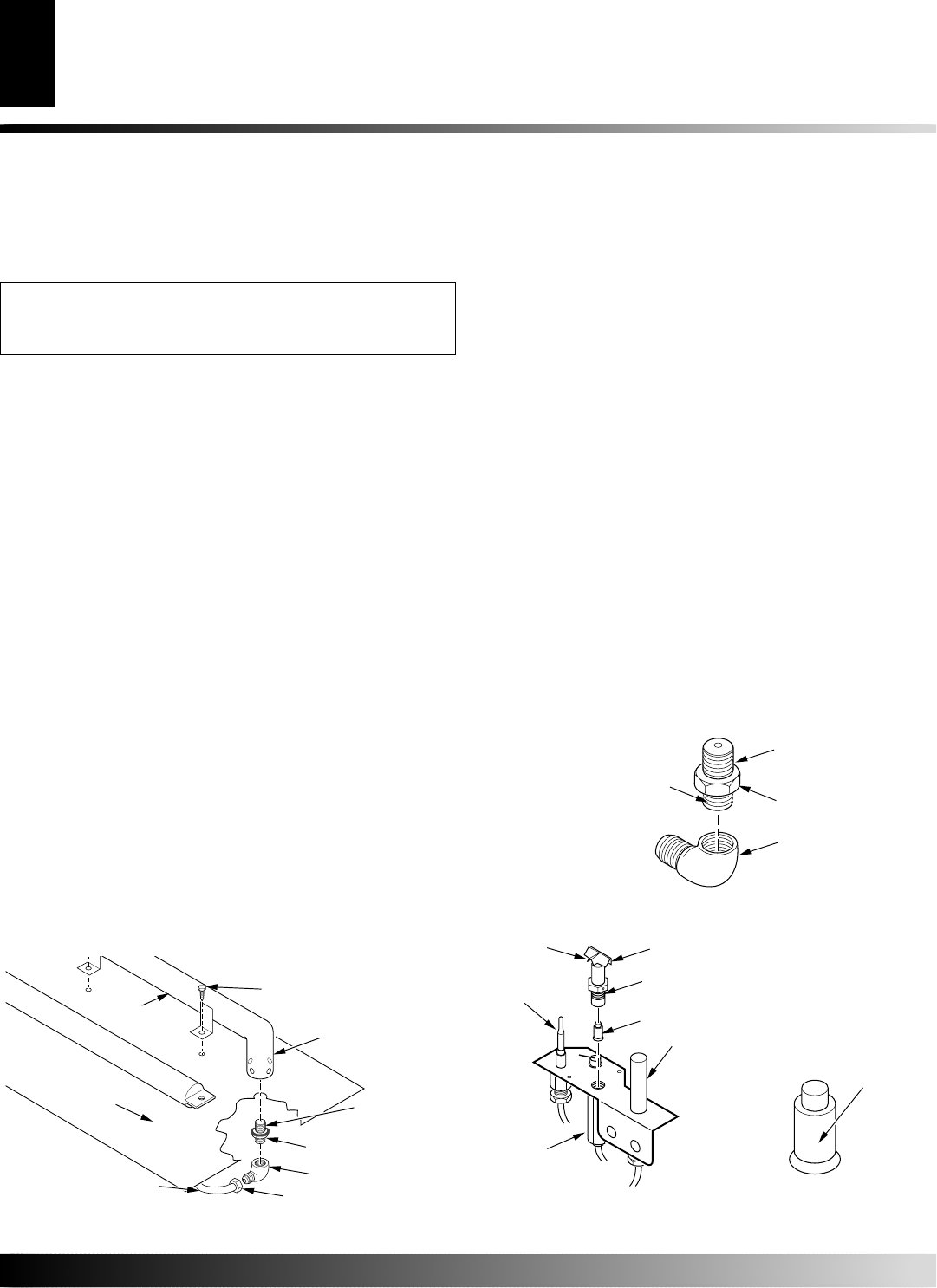
11. Attach main burner orifice and brass elbow assembly to burner.
Place main burner orifice into threaded end of burner and turn
clockwise to tighten (see Figure 12). Align the brass elbow with
the flare fitting on the aluminum tubing.
12. Reconnect the aluminum tube/flare fitting onto the brass elbow
(see Figure 12).
13. Reapply RTV silicone to seal area where orifice passes through
the bottom combustion chamber (see Figure 12).
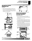
Main Burner Orifice
(18mm Hex)
Brass Elbow
Apply Thread
Sealant Here Only
Figure 13 - Removing/Replacing Main Burner Orifice
x
x
x
x
x
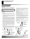
Figure 14 - Removing/Replacing
Pilot Orifice
Pilot Target
Hood
Pilot Target Fitting
(7/16" Hex)
Pilot Orifice
Thermocouple
Thermopile
Stamping
Identification
(014 LP)
Figure 15 - Pilot Orifice
Stamping Identification
Location
Pilot
Barrel
STOVE AND BURNER
SYSTEM ASSEMBLY
Continued
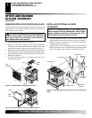
STOVE AND BURNER SYSTEM ASSEMBLY
Installing Propane/LP Conversion Kit
INSTALLING PROPANE/LP CONVERSION KIT
If your burner system is natural gas, do not install
conversion kit. This kit is for users with propane/LP
gas only.
Burner, Main Burner Orifice, and Pilot Orifice
Conversion
1. Front door assembly and glass panel must be removed before
installing conversion kit. See Removing/Replacing Doors and
Glass, page 6.
2. Locate gas line connections and gas control valve inside fire-
box. Disconnect flare fitting connected to the brass elbow from
the underside of stove insert. Use a 3/4" open end wrench on the
flare fitting (see Figure 12).
3. Turn brass elbow and main burner orifice counterclockwise to
remove from burner. The main burner orifice is threaded into
the burner inlet. The brass elbow may have a slight resistance
since the main burner orifice has been sealed with RTV sili-
cone thread sealant. Use a 7/8" open end wrench or channel
lock pliers for brass elbow and main burner orifice removal.
4. Remove existing main burner orifice from brass elbow and re-
place with main burner orifice supplied with conversion kit.
Note:
The new main burner orifice will have the number 151
stamped on it for identification purposes. Apply a small amount
of thread sealant to the main burner orifice before tightening
(see Figure 13). Sealant must be resistant to propane/LP gas.
5. Remove the burner (located inside combustion chamber) by
loosening the two 5/16" hex mounting screws (see Figure 12).
Lift burner up and out.
6. Convert the pilot burner by changing out the quick change ori-
fice.
Note:
It is not necessary to remove the pilot gas tube for
conversion. Using a 7/16" open end wrench, turn pilot target
hex fitting counterclockwise and remove (see Figure 14).
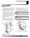
Fireplace
Floor
Burner
Main Burner Orifice
RTV Silicone
Thread Sealant
Brass Elbow
Flare Fitting
Aluminum Tubing
Figure 12 - Removing Main Burner Orifice, Brass Elbow, and
Aluminum Tubing
Mounting Screw
(5/16" Hex)
Primary Air
Holes (4)
Stamping
Identification (151)
Points
Towards
Burner