


111739-01A
For more information, visit www.desatech.com
For more information, visit www.desatech.com
10
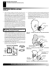
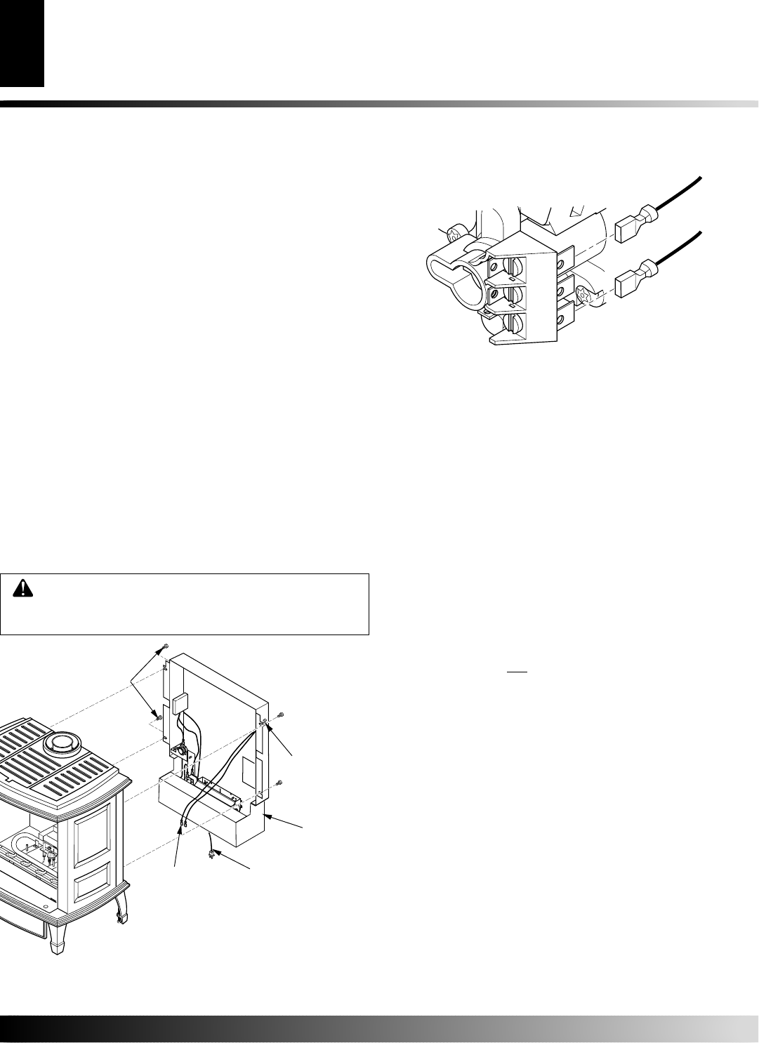
TPTH
TPTH
TP
TP
TH
TH
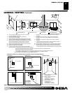
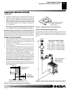
LOCATION OF VENT TERMINATION
When locating vent termination, it is important to observe the
minimum clearances shown in Figure 23, page 11.
*Check with local codes or with the current CAN/CSA B149[.1 or .2]
Installation Codes for Canada or the USA Installations follow the
current National Fuel Gas Code, ANSI Z223.1/NFPA 54.
GENERAL VENTING
Your stove with burner system is approved to be vented either
through the side wall, or vertically using the following guidelines:
• Use only venting components or kits specifically approved for
use with this stove and burner system (see Parts Lists for Vent-
ing Kits and Components, page 19).
IMPORTANT:
Do not mix venting components made by differ-
ent manufacturers.
• Minimum clearance between vent pipes and combustible mate-
rials is 1" (2.5 cm), except where stated otherwise.
• Do not recess venting terminations into a wall or siding.
• Install horizontal venting with a 1/4" rise for every 12" of
run toward the termination.
• You may paint the vent termination with 450ºF (232ºC) heat-
resistant paint to coordinate with the exterior finish.
• There must not be any obstruction such as bushes, garden sheds,
fences, decks, or utility buildings within 24" from the front of
the termination cap.
• Do not locate termination cap where excessive snow or ice build
up may occur. Be sure to clear vent termination area after snow
falls to prevent accidental blockage of venting system. When
using snow blowers, do not direct snow towards vent termina-
tion area.
• You must maintain minimum wall and ceiling clearances shown
in Figures 3 and 4, page 5.
• If installing horizontal vent termination cap on an exterior wall
with siding, you must us a vinyl siding standoff (see Figure 29,
page 14).
To Control
Switch
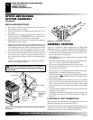
STOVE AND BURNER
SYSTEM ASSEMBLY
Continued
STOVE AND BURNER SYSTEM ASSEMBLY
Installing Rear Cover
GENERAL VENTING
Location of Vent Termination
WARNING: A qualified installer or service per-
son must connect fireplace to gas supply. Follow all
local codes.
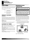
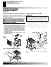
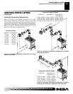
INSTALLING REAR COVER
1. Place rear cover behind stove body. Rear cover will rest on the
bottom ledge of the stove body.
2. Place wire harness from ON/OFF switch under the cast of
stove body.
3. Using hex screws provided, attach rear cover to back of stove
body. See Figure 21.
IMPORTANT:
This rear cover must be
securely in place before venting pipes are installed.
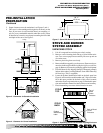
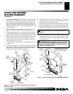
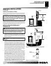
4. Open lower door panel. The valve is attached to the underside
of the burner system assembly.
5. Connect one terminal of the wire from ON/OFF switch to the
THTP terminal on the valve. Connect remaining wire terminal to
the TH terminal on the valve. Make sure that the wire terminals
are in the positions on the unit as pictured in Figure 22. If wires
are not connected as shown, the ON/OFF switch will not work.
6. Move stove to desired installation location. See Location and
Space Requirements, page 4 for proper installation. Refer to
step 17 under Safety Information, page 3, for acceptable floor-
ing types.
7. Connect or reconnect gas supply, see Connecting Stove/Burner
System to Gas Supply on page 21.
Figure 21 - Installing Rear Cover (Shown with Optional Blower
Accessory)
Rear Cover
(Shown with
Optional
Blower)
Hex Screws
Blower
Power
Cord
ON/OFF
Switch Wire
Harness
ON/OFF Switch
Figure 22 - Control Valve Terminals