www.desatech.com
117437-01D 23
INSPECTING BURNERS
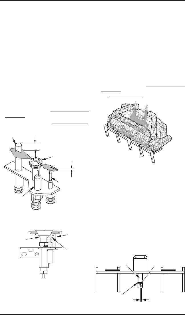
Thermocouple
Thermopile
1/4"
Pilot Burner
Ignitor
Figure 38 - Pilot Assembly
(Millivolt Ignition System)
3/8" to 1/2"
Sensor
Rod
Pilot
Burner
Ignitor
Figure 39 - Pilot Assembly
Electronic Ignition System)
patterns often.
PILOT ASSEMBLY
The pilot assembly is factory preset for
occurred during shipping and handling. Call
if necessary.
-
tion to sensing devices should be as shown
in Figures 38 and 39 respectively.
If your pilot assembly does not meet these
requirements:
To Turn Off Gas to
Appliance
• see sections under Troubleshooting
page 25
Figure 40 - Typical Flame Pattern
Figure 41 - Adjusting Air Setting
AIR ADjUSTMENT SETTING
The main burner air shutter opening is factory
set to the following:
-
-
properly lighting shutter may require closing.
IMPORTANT: Do not reduce air shutter open-
ing any lower than designed minimum stop
setting of 1/8".
1/8" Minimum
Air Opening
Air
Shutter
Burner
Tube
Screw
BURNER FLAME PATTERNS
to unit and will vary depending on installation
type and weather conditions.
-
proper installation and performance. Figure 40
-
scribed:
To Turn Off Gas to
Appliance
• see Troubleshooting


