


www.desatech.com
15111168-01A
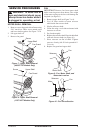
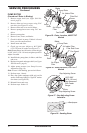
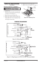
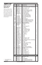
IGNITION CONTROL ASSEMBLY
WARNING: High Voltage!
1. Unplug heater.
2. Remove side cover screws (4) using 5/16"
nut-driver to expose ignition control assembly
(see Figure 15 or 16, page 11).
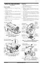
3. Remove fuse cover (see Figure 29).
4. Remove fuse from fuse clips (see Figure 29).
5. Replace fuse with fuse of the same type and
rating (GMA-10). Do not substitute a fuse
with a higher current rating.
Figure 29 - Replacing Fuse
Fuse
Fuse
Cover
Fuse
Clips
6. Replace fuse cover (see Figure 29).
7.
Replace side cover (see Figure 15 or 16, page 11).
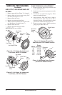
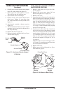
Power Plug
120V/60Hz
Blue
Blue
White
White
Photocell
Ignition Control Assembly
Green
Green
Red
Black
Black
Yellow
Yellow
Motor
Ignitor
Thermostat
Photocell
Photocell
Ignitor
Motor Return
AC Neutral (L2)
120V (L1)
Ignitor
Motor
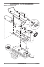
Figure 31 - Wiring Diagram for 55T/70T/115T/165T Thermostat Models
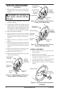
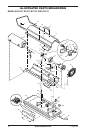
Power Plug
120V/60Hz
Blue
Blue
White
White
Photocell
Green
Green
Red
Black
Ye
llow
Yellow
Motor
Ignitor
Ignition Control Assembly
Photocell
Photocell
Ignitor
Motor Return
AC Neutral (L2)
120V (L1)
Ignitor
Motor
Figure 30 - Wiring Diagram for 40 Models
WIRING DIAGRAMS
SERVICE PROCEDURES
Continued