


www.desatech.com
111168-01A
14
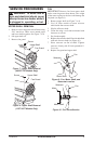
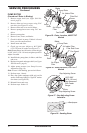
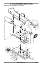
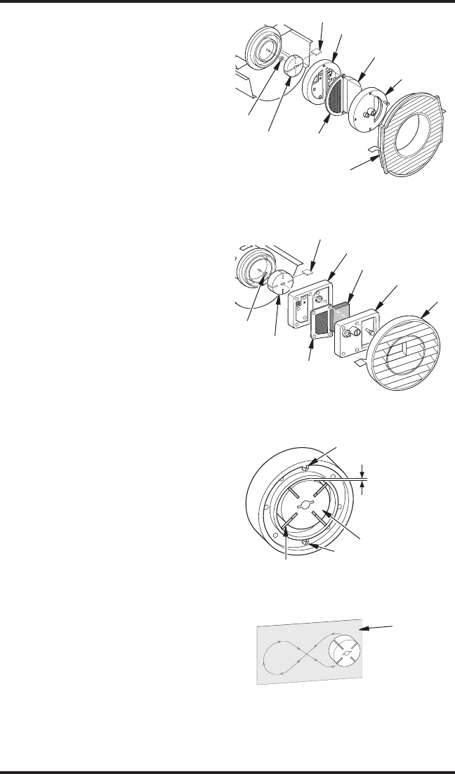
PUMP ROTOR
(Procedure if Rotor is Binding)
1. Remove upper shell (see Upper Shell Re
-
moval, page 9).
2. Remove filter end cover screws using 5/16"
nut-driver (see Figure 25 or 26).
3. Remove filter end cover and air filters.
4. Remove pump plate screws using 5/16" nut-
driver.
5. Remove pump plate.
6. Remove rotor, insert, and blades.
7. Check for debris in pump. If debris is found,
blow out with compressed air.
8. Install insert and rotor.
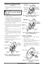
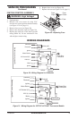
9. Check gap on rotor. Adjust to .003"/.004"
(.076-.101 mm) if needed (see Figure 27).
Note: Rotate Rotor one full turn to insure the gap
is .003"/.004" (.076-.101 mm) at tightest position.
Adjust if needed.
10. Install blades, pump plate, air filters, and filter
end cover.
11. Replace fan guard and upper shell (see
Upper
Shell Removal, page 9).
12. Adjust pump pressure (see Pump Pressure
Adjustment, page 10).
Note: If rotor is still binding, proceed as follows.
13. Perform steps 1 thru 6.
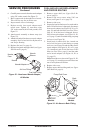
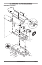
14. Place fine grade sandpaper (600 grit) on flat
surface. Sand rotor lightly in “figure 8” motion
four times (see Figure 28).
15. Reinstall insert and rotor.
16. Perform steps 10 thru 12.
Figure 26 - Rotor Location, 115T/165T
Models
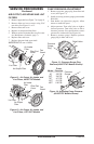
Figure 25 - Rotor Location, 40/55T/70T
Models
Rotor
Air Output
Filter
Insert
Fan Guard
Filter End
Cover
Air Intake Filter
Blade
Pump Plate
Insert
Rotor
Air Output
Filter
Blade
Filter End Cover
Air Intake Filter
Pump Plate
Fan Guard
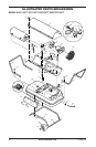
Gap Adjusting Screw
Rotor
Blade
.003"/.004"
(.076-.101 mm)
Gap Measured
With Feeler
Gauge
Gap Adjusting Screw
Figure 27 - Gap Adjusting Screw
Locations
Sandpaper
Figure 28 - Sanding Rotor
SERVICE PROCEDURES
Continued