


www.desatech.com
11
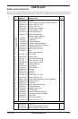
111168-01A
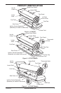
Fuel Filter, Bushing,
and Lower Fuel Line
Upper Fuel Line
Side
Cover
Fuel Filter
Side
Cover
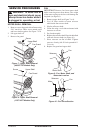
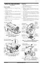
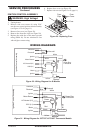
Figure 15 - Fuel Filter Removal,
40/55T/70T Models
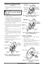
Figure 16 - Fuel Filter Removal,
115T/165T Models
Upper Fuel Line
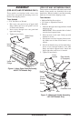
FUEL FILTER
1. Remove side cover screws using 5/16" nut-
driver.
2. Remove side cover.
3. Pull upper fuel line off fuel filter neck (see
Figure 15 or 16).
4. Carefully pry bushing, fuel filter, and lower
fuel line (115T/165T models only) out of fuel
tank (see Figure 16).
5. Wash fuel filter with clean fuel and replace in
tank.
6. Attach upper fuel line to fuel filter neck.
7. Replace side cover.
SERVICE PROCEDURES
Continued
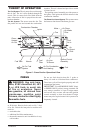
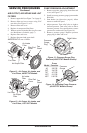
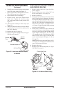
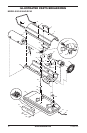
Figure 17 - Disconnecting Ignitor Wires
from Ignition Control Assembly
Combustion
Chamber
Photocell
Bracket
Photocell
Assembly
Air Line
Hose
Fuel Line
Hose
Ignitor Wire
(Yellow)
Ignitor
Nozzle
Adapter
Bracket
Ignition
Control
Assembly
Side Cover
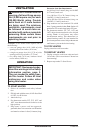
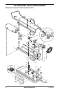
Photocell
Bracket
Ignitor
Ignitor Screw/
Washer Assembly
Nozzle
Adapter
Bracket
Ignitor Element
Combustion Chamber
Nozzle Adapter
Bracket Opening
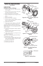
Figure 18 - Ignitor Replacement
IGNITOR
1. Remove upper shell and fan guard (See Upper
Shell Removal, page 9).
2. Remove fan (see page 9).
3.
Remove 4 side cover screws with a 5/16"
nut driver. Remove side cover (see Figures
15 and 16).
4. Disconnect ignitor wires (yellow) from igni-
tion control assembly (see Figure 17). Pull
the ignitor wires up through the hole in the
lower shell.
5. Disconnect fuel line hose and air line hose.
Remove photocell from photocell bracket (see
Figure 17).
6. Remove combustion chamber. Stand com
-
bustion chamber on end with nozzle adapter
bracket on top (see Figure 18).