


www.desatech.com
13111168-01A
SERVICE PROCEDURES
Continued
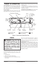
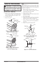
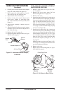
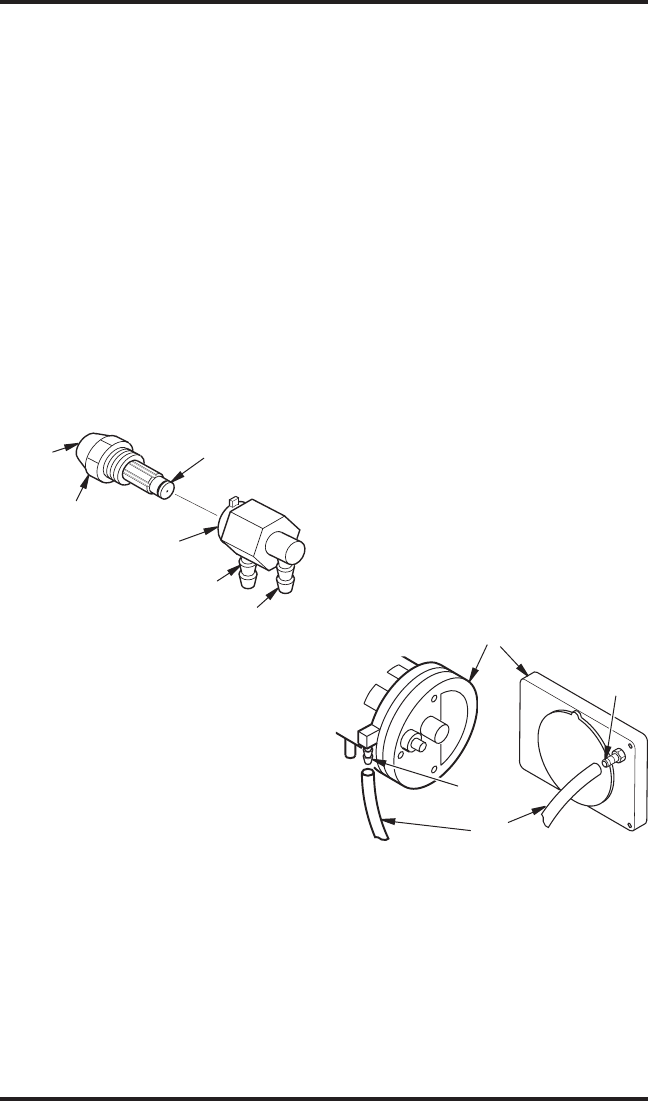
Air Line Fitting
Fuel Line Fitting
Nozzle
Nozzle
Sleeve
Nozzle
Face
Figure 23 - Nozzle and Nozzle Adapter,
All Models
Nozzle Adapter
6. Carefully remove nozzle from the nozzle adapter
using 5/8" socket wrench. See Figure 23.
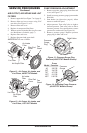
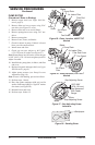
7. Blow compressed air through face of nozzle.
This will free any dirt in nozzle area.
8. Inspect nozzle sleeve for damage.
9. Replace nozzle into nozzle adapter until
nozzle seats. Tighten 1/3 turn more using
5/8" socket wrench (40-45 inch-pounds). See
Figure 23.
10. Attach nozzle assembly to burner strap (see
Figure 22).
11. Attach fuel and airline hoses to nozzle adapter
assembly. See Fuel and Air Line Replacement
and Proper Routing
.
12. Replace fan (see
Fan, page 9).
13. Replace fan guard and upper shell (see
Upper
Shell Removal, page 9).
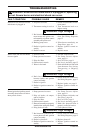
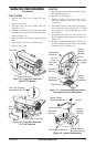
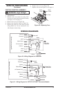
Barb
Fitting
Air Hose
Pump End Cover
Barb
Fitting
115T/165T
Models
40/55T/70T
Models
Figure 24 - Air Hose to Barb Fitting
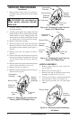
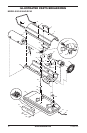
FUEL AND AIR LINE REPLACEMENT
AND PROPER ROUTING
1. Remove upper shell (see Upper Shell Re-
moval, page 9).
2. Remove side cover screws using 5/16" nut
driver (see Figure 15 or 16, page 11).
3. Remove side cover.
4. Inspect fuel and air line hoses for cracks and/or
holes. If fuel line hose is damaged, disconnect
from nozzle adapter (see Figure 19, 20, or 21,
page 12) and from fuel filter (see Fuel Filter
,
page 11). If air line hose is damaged, discon
-
nect from nozzle adapter (see Figure 19, 20,
or 21, page 12) and from barb fitting on pump
end cover (see Figure 24).
5. Install new air and/or fuel line. Attach one
end of air line hose to barb fitting on pump
end cover (see Figure 24) and the other end to
nozzle adapter (see Figure 19, 20, or 21, page
12). Attach one end of fuel line hose to fuel
filter (see Fuel Filter, page 11) and the other
end to nozzle adapter (see Figure 19, 20, or
21, page 12).
Note: Route hoses as shown in Figure 19, 20,
or 21, page 12, according to model. Hoses are
not to touch photocell bracket.
6. Replace side cover.
7. Replace upper shell and fan guard (see
Upper
Shell Removal, page 9).