


www.desatech.com
5111168-01A
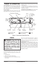
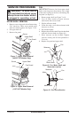
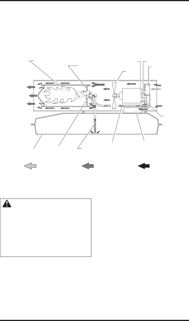
THEORY OF OPERATION
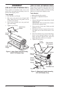
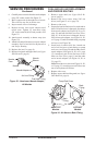
The Fuel System: The air pump forces air through
the air line. The air is then pushed through the
nozzle. This air causes fuel to be lifted from the
tank. A fine mist of fuel is sprayed into the com-
bustion chamber.
The Air System: The motor turns the fan. The
fan pushes air into and around the combustion
Figure 6 - Cross Section Operational View
Clean
Heated
Air Out
Fuel
Filter
Air
Output
Filter
Air Pump
Air Intake
Filter
Cool
Air In
Fan
Combustion Chamber
Ignitor
Motor
Air For Fuel
System
Air For Combustion
And Heating
Fuel
Nozzle
Fuel Tank
Ignition Control
Assembly
Air Line
To Burner
chamber. This air is heated and provides a stream
of clean, hot air.
The ignition control assembly provides power to
the ignitor. This ignites the fuel/air mixture in the
combustion chamber.
The Flame-Out Control System: This system causes
the heater to shut down if the flame goes out.
FUELS
WARNING: Use only kero-
sene, #1/#2 diesel/fuel oil, JET
A or JP-8 fuels to avoid risk
of fire or explosion. Never
use gasoline, oil drained from
crankcases, naphtha, paint
thinners, alcohol or other highly
flammable fuels.
Use only kerosene, #1/#2 diesel/fuel oil, JET A
or JP-8 fuels. Heavier fuels such as No. 2 fuel
oil or No. 2 diesel fuel may also be used but will
result in:
• noticeable odor
• additional fuel filter maintenance
• the need for nontoxic, anti-icer additives in very
cold weather
Do not use fuels heavier than No. 2 grade or
heavy oils such as oil drained from crankcases.
These heavy oils will not ignite properly and will
contaminate the heater.
IMPORTANT: Use a KEROSENE ONLY (blue)
or DIESEL ONLY (yellow) storage container. Be
sure storage container is clean. Foreign matter
such as rust, dirt, or water will cause the ignition
control assembly to shut down heater. Foreign
matter may also require heater's fuel system to be
frequently cleaned.