


9
104193
OWNER’S MANUAL
SERVICE
PROCEDURES
Continued
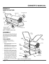
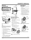
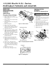
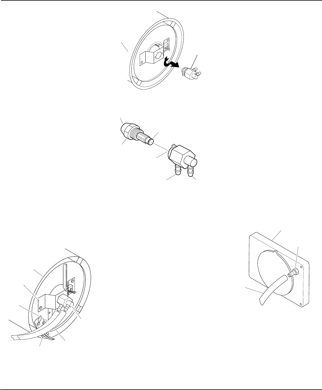
Figure 12 - Removing Air and Fuel Line
Hoses
Nozzle/
Adapter
Assembly
Combustion
Chamber
Figure 13 - Removing Nozzle/Adapter
Assembly
Nozzle Face
Nozzle
Nozzle
Seal
Nozzle
Adapter
Air Line
Fitting
Fuel Line
Fitting
Figure 14 - Nozzle and Nozzle Adapter
NOZZLE ASSEMBLY
1. Remove upper shell (see page 7).
2. Remove fan (see page 7).
3. Remove fuel and air line hoses from
nozzle assembly (see Figure 12).
4. Turn nozzle assembly 1/4 turn to left
and pull toward motor to remove (see
Figure 13).
5. Place plastic hex-body into vise and
lightly tighten.
6. Carefully remove nozzle from the
nozzle adapter using 5/8" socket wrench
(see Figure 14).
7. Blow compressed air through face of
nozzle. This will free any dirt in nozzle area.
8. Inspect nozzle seal for damage.
9. Replace nozzle into nozzle adapter un-
til nozzle seats. Tighten 1/3 turn more
using 5/8" socket wrench (40-45 inch-
pounds). See Figure 14.
10. Attach nozzle assembly to burner strap.
11. Attach fuel and airline hoses to nozzle
assembly. See Fuel and Air Line Re-
placement and Proper Routing.
12. Replace fan (see page 7).
13. Replace fan guard and upper shell (see
page 7).
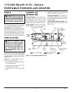
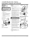
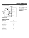
Fuel Line
Hose
Nozzle/
Adapter
Assembly
Combustion
Chamber
Air Line
Hose
Burner
Strap
Photocell
Bracket
FUEL AND AIR LINE
REPLACEMENT AND
PROPER ROUTING
1. Remove upper shell (see page 7).
2. Remove side cover screws using 5/16"
nut driver.
3. Remove side cover.
4. Inspect fuel and air line hoses for cracks
and/or holes. If fuel line hose is dam-
aged, disconnect from nozzle adapter
(see Figure 12) and from fuel filter (see
page 8). If air line hose is damaged, dis-
connect from nozzle adapter (see Fig-
ure 12) and from barb fitting on pump
end cover (see Figure 15).
5. Install new air and/or fuel line. Attach
one end of air line hose to barb fitting
on pump end cover (see Figure 15) and
the other end to nozzle adapter (see Fig-
ure 12). Attach one end of fuel line hose
to fuel filter (see page 8) and the other
end to nozzle adapter (see Figure 12).
Route air and fuel line approximately
as shown in Figure 12.
Note:
Hoses are not to be touching pho-
tocell bracket.
6. Replace side cover.
7. Replace upper shell and fan guard (see
page 7).
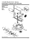
Figure 15 - Air Hose to Barb Fitting
Barb Fitting
Air Hose
Pump End Cover
Continued