


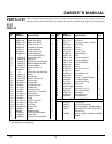
7
104193
OWNER’S MANUAL
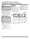
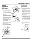
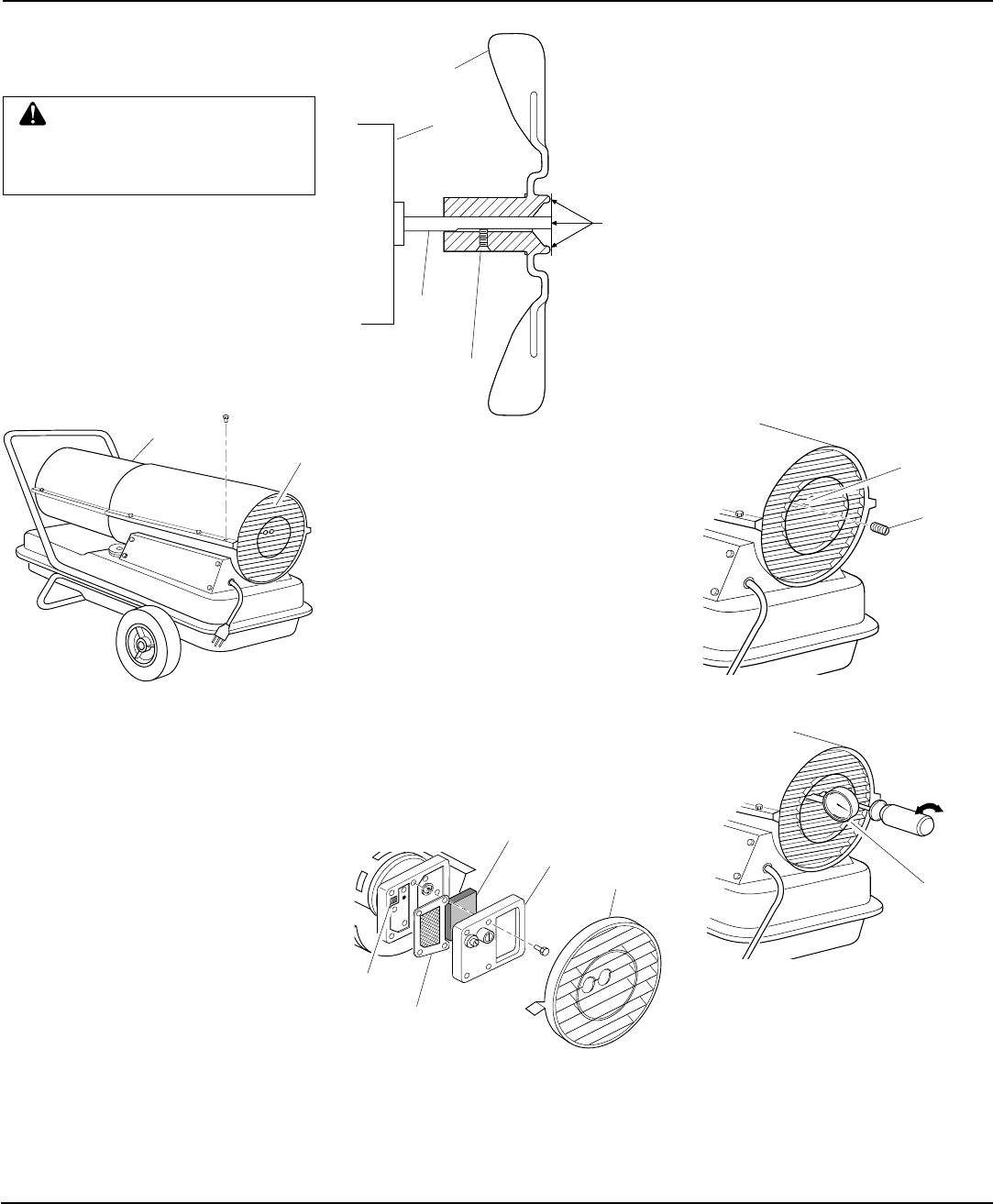
Figure 7 - Pressure Gauge Plug Removal
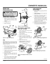
Fan
Motor
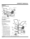
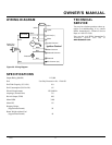
Figure 6 - Air Output, Air Intake, and Lint
Filters
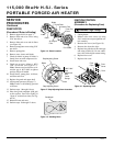
Flush
Setscrew
Motor
Shaft
Figure 5 - Fan Cross Section
SERVICE
PROCEDURES
WARNING: Never service
heater while it is plugged in, op-
erating, or hot. Severe burns and
electrical shock can occur.
UPPER SHELL REMOVAL
1. Remove screws along each side of
heater using 5/16" nut-driver. These
screws attach upper and lower shells
together.
2. Lift upper shell off.
3. Remove fan guard.
FAN
IMPORTANT:
Remove fan from motor shaft
before removing motor from heater. The
weight of the motor resting on the fan could
damage the fan pitch.
1. Remove upper shell (see above).
2. Use 1/8" Allen wrench to loosen set-
screw which holds fan to motor shaft.
3. Slip fan off motor shaft.
4. Clean fan using soft cloth moistened
with kerosene or solvent.
5. Dry fan thoroughly.
6. Replace fan on motor shaft. Place fan
hub flush with end of motor shaft (see
Figure 5).
7. Place setscrew on flat of shaft. Tighten
setscrew firmly (40-50 inch-pounds).
8. Replace fan guard and upper shell.
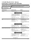
AIR OUTPUT, AIR INTAKE,
AND LINT FILTERS
1. Remove upper shell (see Upper Shell
Removal, column 1).
2. Remove filter end cover screws using
5/16" nut-driver.
3. Remove filter end cover.
4. Replace air output and lint filters.
5. Wash or replace air intake filter (see
Preventative Maintenance Schedule,
page 5).
6. Replace filter end cover.
7. Replace fan guard and upper shell.
IMPORTANT:
Do not oil filters.
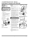
PUMP PRESSURE
ADJUSTMENT
1. Remove pressure gauge plug from filter
end cover.
2. Install accessory pressure gauge (part
number HA1180).
3. Start heater (see Operation, page 5).
Allow motor to reach full speed.
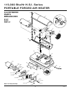
4. Using a flat blade screwdriver, adjust
pressure. Turn relief valve to right to
increase the pressure. Turn relief valve
to left to decrease the pressure. Set
pump pressure at 5.3 PSI.
5. Stop heater (see Operation, page 5).
6. Remove pressure gauge. Replace pres-
sure gauge plug in filter end cover.
Figure 4 - Upper Shell Removal
Upper
Shell
Fan
Guard
Fan Guard
Air Intake Filter
Air Output Filter
Filter End Cover
Lint Filter
Relief
Valve
Pressure
Gauge
Plug
Pressure
Gauge
Figure 8 - Adjusting Pump Pressure
Continued