


6
104193
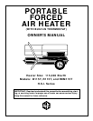
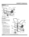
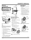
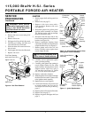
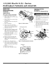
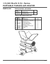
PORTABLE FORCED AIR HEATER
115,000 Btu/Hr H.S.I. Series
TROUBLESHOOTING
WARNING: Never service heater while it is plugged in, operating, or
hot. Severe burns and electrical shock can occur.
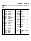
OBSERVED FAULT
Motor does not start five seconds after heater
is plugged in
Motor starts and runs but heater does not
ignite
Heater ignites but ignition control assembly
shuts heater off after a short period of time
POSSIBLE CAUSE
1. No power to heater
2. Thermostat setting too low
3. Bad electrical connection between mo-
tor and ignition control assembly or ig-
nition control assembly and power cord
4. Blown fuse on ignition control assembly
5. Binding pump rotor
6. Defective ignition control assembly
7. Defective motor
1. No fuel in tank
2. Pump pressure incorrect
3. Dirty fuel filter
4. Obstruction in nozzle assembly
5. Water in fuel tank
6. Bad electrical connection between igni-
tor and ignition control assembly
7. Defective ignitor
8. Defective ignition control assembly
1. Pump pressure incorrect
2. Dirty air intake, air output, and/or lint
filter
3. Dirty fuel filter
4. Obstruction in nozzle assembly
5. Photocell assembly not properly installed
(not seeing the flame)
6. Dirty photocell lens
7. Bad electrical connection between pho-
tocell and ignition control assembly
8. Defective photocell
9. Defective ignition control assembly
REMEDY
1. Check circuit breaker in electrical panel
2. Turn thermostat knob to a higher setting
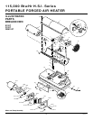
3. Check all electrical connections. See
Wiring Diagram, page 11
4. See Ignition Control Assembly, page 10
5. If fan does not turn freely, see Pump
Rotor, page 10
6. Replace ignition control assembly
7. Replace motor
1. Fill tank with kerosene
2. See Pump Pressure Adjustment, page 7
3. See Fuel Filter, page 8
4. See Nozzle Assembly, page 9
5. Drain and flush fuel tank with clean kero-
sene. See Storing, Transporting, or Ship-
ping, page 5
6. Check electrical connections. See Wir-
ing Diagram, page 11
7. Replace ignitor, see page 8
8. Replace ignition control assembly
1. See Pump Pressure Adjustment, page 7
2. See Air Output, Air Intake, and Lint Fil-
ters, page 7
3. See Fuel Filter, page 8
4. See Nozzle Assembly, page 9
5. Make sure photocell boot is properly
seated in bracket
6. Clean photocell lens
7. Check electrical connections. See Wir-
ing Diagram, page 11
8. Replace photocell
9. Replace ignition control assembly
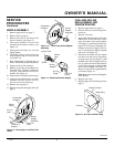
WARNING: High voltage!
WARNING: High voltage!
WARNING: High voltage!
Note:
For additional help, visit DESA
International’s Technical Service web
site at www.desatech.com.
www.desatech.com